
Pulse power supply used in electric precipitation

A technology of pulse power supply and electrostatic precipitator, which is applied in the field of design of electrostatic precipitator equipment, can solve the problems affecting the performance of the precipitator, uneven charge distribution, back corona, etc., to prevent back corona phenomenon, simplify the circuit structure, increase the The effect of scope

Inactive Publication Date: 2013-10-16
浙江菲达环保科技股份有限公司
View PDF5 Cites 20 Cited by
  • Summary
  • Abstract
  • Description
  • Claims
  • Application Information

AI Technical Summary

Problems solved by technology

The dust removal efficiency of the electrostatic precipitator depends on the driving speed of the charged dust, and the driving speed is proportional to the peak value of the secondary voltage (that is, the peak voltage of dust removal) and the particle size of the dust, but limited by the power, the secondary of the traditional electrostatic precipitator The voltage peak cannot meet the requirements of some large particle dust removal
At the same time, with the continuous accumulation of dust on the dust collector of the electrostatic precipitator, due to the uneven distribution of residual charges in the dust, there will be a back corona phenomenon, and the back corona will recombine the negative ions in the dust collector, which will affect the performance of the dust collector
[0003] For this reason, there is a Chinese patent with publication number CN102847610A disclosing a DC composite pulse high-voltage power supply for electrostatic precipitators. The three-phase AC current is rectified and then connected to a resonant circuit. The resonant circuit is an electronic switch formed by antiparallel connection of a diode and a thyristor. To control the generation of pulse high voltage, it is necessary to set up a composite circuit to compound the high pulse voltage and DC voltage under the action of pulse high voltage and DC voltage to increase the peak value of the secondary voltage. At the same time, the pulse high voltage also prevents the generation of back corona, but its circuit structure It is necessary to set up a special composite circuit to increase the complexity of the circuit, and at the same time, it is impossible to adjust the energy of the single pulse voltage, which affects the scope of application

Method used


Image

  • Pulse power supply used in electric precipitation

Examples


Embodiment Construction

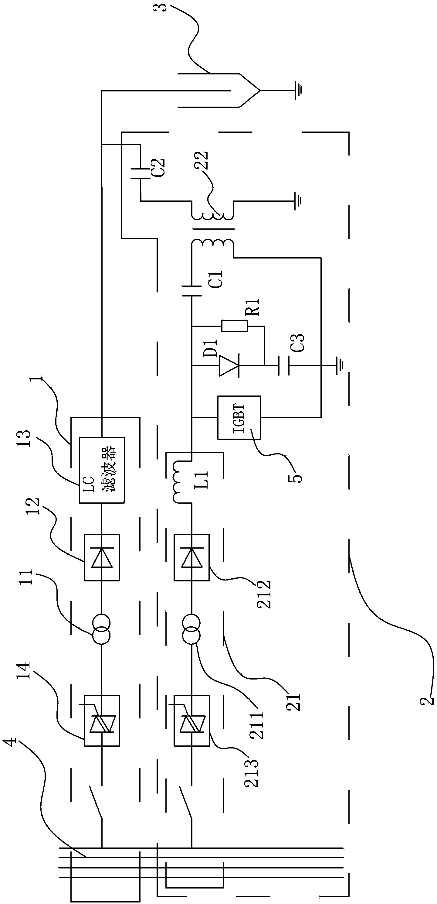
[0015] Such as figure 1 As shown, a pulse power supply for electric dust removal includes a DC high-voltage power supply circuit 1 and a pulse high-voltage power supply circuit 2. The DC high-voltage power supply circuit 1 is connected to the dust collector 3 and does not provide a basic voltage for the dust collector 3 to start the dust removal program. The power supply circuit 2 is coupled to the DC high-voltage power supply circuit 1, and the DC high-voltage power supply circuit 1 and the pulse high-voltage power supply circuit 2 share a low-voltage AC power supply 4. In actual use, the low-voltage AC power supply 4 is a low-voltage three-phase AC power supply. The pulse high-voltage power supply circuit includes an AC-DC conversion circuit 21 and a pulse transformer 22. The AC-DC conversion circuit 21 includes a low-voltage AC power supply 4 connected in series, a first step-up transformer 211, a first rectifier bridge 212 and a smoothing inductance L1. The step-up transfo...


PUM


Abstract

The invention discloses a pulse power supply used in electric precipitation. An existing precipitator adopts a direct-current composite pulsed high-voltage power supply with a complicated circuit structure. The power supply provided by the invention comprises a direct-current high-voltage power supply circuit and a pulse high-voltage power supply circuit. The direct-current high-voltage power supply circuit is electrically connected to the precipitator. The pulse high-voltage power supply circuit and the direct-current high-voltage power supply circuit which are coupled provide power for the precipitator. The pulse high-voltage power supply circuit comprises an AC-DC converter circuit and a pulse transformer. One end of a primary side of the pulse transformer is connected to the AC-DC converter circuit through a storage capacitor, and is grounded with the other end of the primary side of the pulse transformer through an electronic switch. One end of a secondary side of the pulse transformer is connected to a joint point of the direct-current high-voltage power supply circuit and the precipitator through a high-voltage coupling capacitor, and the other end is grounded. According to the invention, the coil of the pulse transformer is utilized, and the equivalent capacitance of a precipitator electric field is utilized, such that the circuit of the power supply provided by the invention is simplified.

Description

technical field [0001] The invention designs electric dust collector equipment, specifically refers to a pulse power supply for electric dust removal. Background technique [0002] The traditional electrostatic precipitator adopts a high-voltage DC dust removal power supply. The negative electrode of the dust removal power supply is connected to the corona electrode to generate corona discharge, which charges the dust particles, and under the action of the electric field force, the dust particles are separated from the gas and treated. collect. The dust removal efficiency of the electrostatic precipitator depends on the driving speed of the charged dust, and the driving speed is proportional to the peak value of the secondary voltage (that is, the peak voltage of dust removal) and the particle size of the dust, but limited by the power, the secondary of the traditional electrostatic precipitator Voltage peaks cannot meet some large particle dust removal requirements. At th...

Claims


Application Information

Patent Timeline
Patent Type & Authority Applications(China)
IPC IPC(8): B03C3/66H02M9/06
Inventor 遇彬章涵姚凌飞
Owner 浙江菲达环保科技股份有限公司
Learn More