Mechanical kinetic energy automatic rise-and-fall netting bracket

A technology of mechanical kinetic energy and bracket, applied in the field of steel cage weaving devices, can solve the problems of steel cage damage, high cylinder maintenance cost, high cylinder cost, high work efficiency, saving maintenance cost and time, and long service life. Effect

Active Publication Date: 2015-01-07
广东宏基管桩有限公司
View PDF7 Cites 0 Cited by
  • Summary
  • Abstract
  • Description
  • Claims
  • Application Information

AI Technical Summary

Problems solved by technology

Existing problems are: high cost of the cylinder, harsh working environment, and high maintenance cost of the cylinder; on the other hand, misoperation often occurs, causing damage to the steel cage

Method used


Image

  • Mechanical kinetic energy automatic rise-and-fall netting bracket
  • Mechanical kinetic energy automatic rise-and-fall netting bracket
  • Mechanical kinetic energy automatic rise-and-fall netting bracket

Examples


Embodiment Construction

[0021] The present invention will be further described below in conjunction with the accompanying drawings.

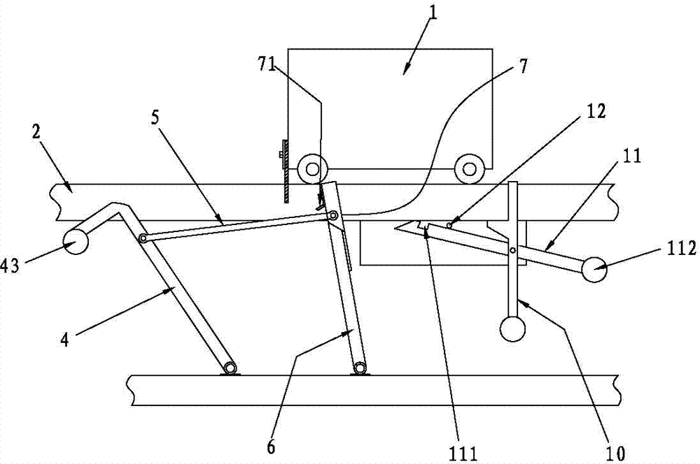
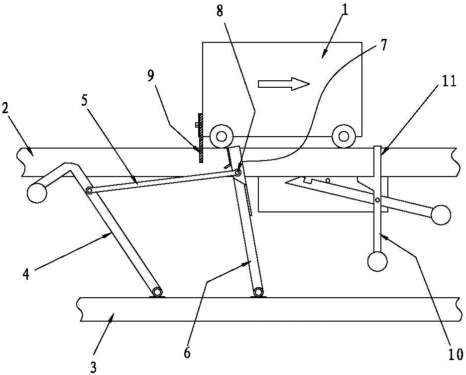
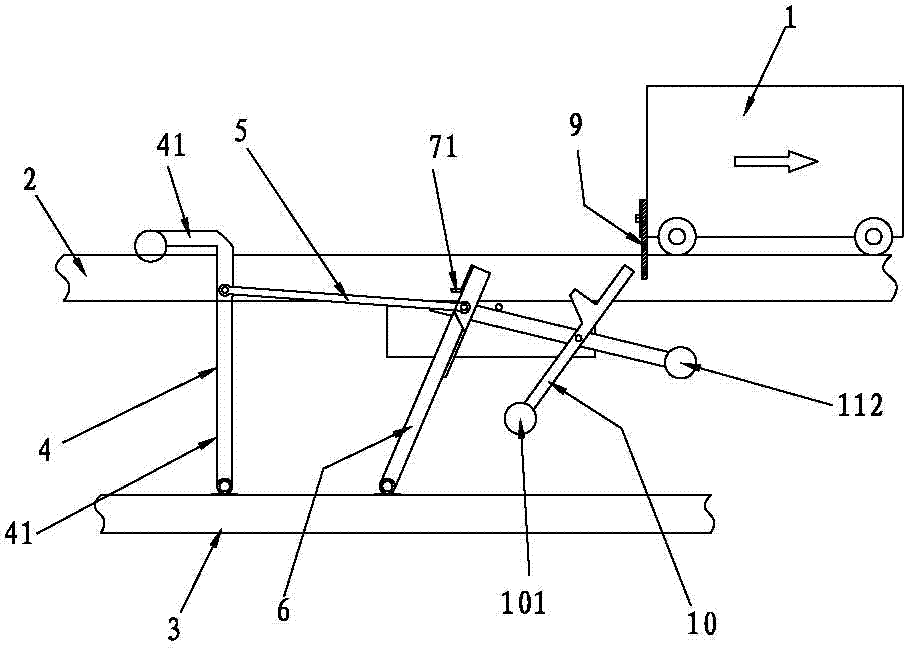
[0022] Such as figure 1 As shown, a mechanical kinetic energy type automatic lifting netting bracket includes a netting trolley 1 with casters on both sides, two guide rails 2, a guide rail base 3 and a bracket 4, the lower end of the bracket 4 is connected to the guide rail base 3 pivot connection, the driving device arranged on the guide rail base 3 cooperates with the bracket 4; the bracket 4 includes two frame bodies, the frame body includes a vertical bar 41 and a cross bar 42, and the cross bar 42 is supported and matched with the steel cage; There is a reset gravity block 43 on the bracket 4 . The reset gravity block 43 is arranged on one end of the cross bar 42 .

[0023] The driving device includes a bracket pull rod 5, a swing rod 6, a one-way flap 7, a tripping plate 71 arranged on the one-way flap 7, a fixed shaft 8, a locking device and a netting trolley...


PUM


Abstract

A mechanical kinetic energy automatic rise-and-fall netting bracket comprises a netting trolley, guide rails, guide rail bases and bracket bodies, wherein castors are arranged on the two sides of the netting trolley. Driving devices comprise bracket pull rods, swing rods, one-way turnover plates, tripping pressing plates arranged on the one-way turnover plates, fixing shafts, locking devices and driving rubber scraper plates arranged on the netting trolley. The lower ends of the swing rods are connected with the guide bases in a pivoting mode. One ends of the bracket pull rods are connected with the bracket bodies in a pivoting mode, and the other ends of the bracket pull rods are connected with the swing rods through the fixing shafts in a pivoting mode. The one-way turnover plates are arranged on the upper portions of the swing rods and connected with the swing rods in a pivoting mode. The driving rubber scraper plates are matched with the on-way turnover plates. The locking devices are matched with the fixing shafts. The tripping pressing plates are matched with the locking devices. By the adoption of the structure, the netting trolley moves back and forth, so that the bracket raises and falls, and using is convenient.

Description

technical field [0001] The invention relates to a device for weaving steel cages for pipe piles, in particular to a device for removing steel cages. Background technique [0002] In the current prior art, a mechanical kinetic energy type automatic lifting netting bracket includes a netting trolley with casters on both sides, a guide rail, a guide rail base, a bracket, a sensor and a cylinder, and the lower end of the bracket is pivoted to the guide rail base. Then, the piston rod of the cylinder is pivotally matched with the bracket. The existing problems are: the cost of the cylinder is high, the working environment is harsh, and the maintenance cost of the cylinder is high; on the other hand, misoperation often occurs, resulting in damage to the steel cage. Contents of the invention [0003] The purpose of the present invention is to provide a mechanical kinetic energy type automatic lifting netting bracket, which can automatically lift up and support the steel cage wit...

Claims


Application Information

Patent Timeline
Patent Type & Authority Patents(China)
IPC IPC(8): B21F31/00
Inventor 何耀晖陈焯辉梁煊林
Owner 广东宏基管桩有限公司
Why Eureka
Try Eureka