
Improved shutter delay measurement system

A measurement system and shutter technology, applied in optics, instruments, photography, etc., can solve the problems of out-of-sync exposure and achieve the effect of improving the accuracy of readings and reducing the complexity of readings

Inactive Publication Date: 2013-10-02
INST OF OPTICS & ELECTRONICS - CHINESE ACAD OF SCI
View PDF4 Cites 24 Cited by
  • Summary
  • Abstract
  • Description
  • Claims
  • Application Information

AI Technical Summary

Problems solved by technology

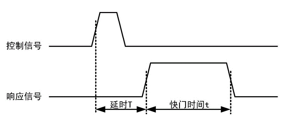
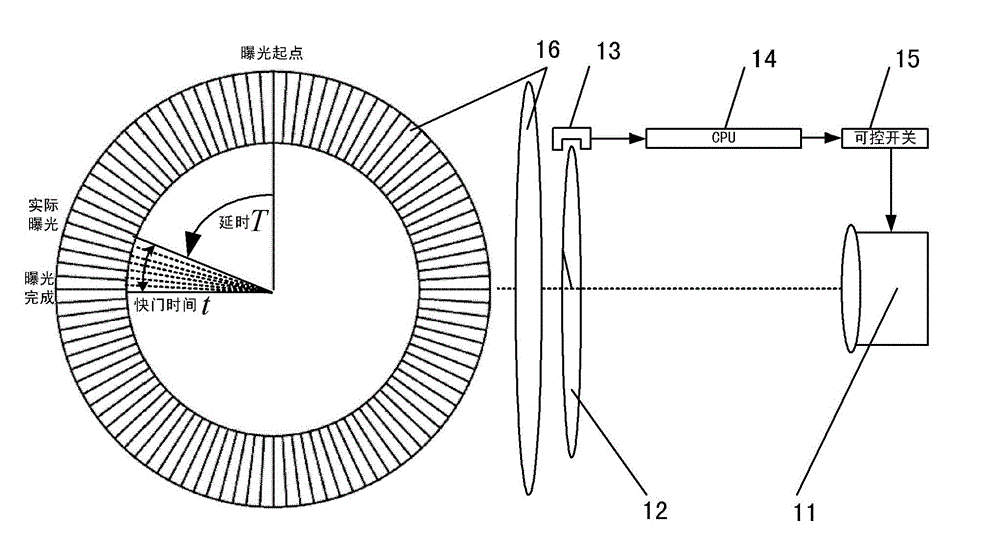
[0007] The purpose of the present invention is to solve the problem of out-of-sync exposure in the process of multi-camera stitching in view of the limitations of the prior art, and to provide an improved camera shutter delay measurement system, which compensates for the shutter delay in the multi-camera stitching system , to provide a basis for synchronous exposure

Method used


Image

  • Improved shutter delay measurement system
  • Improved shutter delay measurement system
  • Improved shutter delay measurement system

Examples


Embodiment Construction

[0017] In order to make the object, technical solution and advantages of the present invention clearer, the present invention will be described in further detail below in conjunction with specific embodiments and with reference to the accompanying drawings.

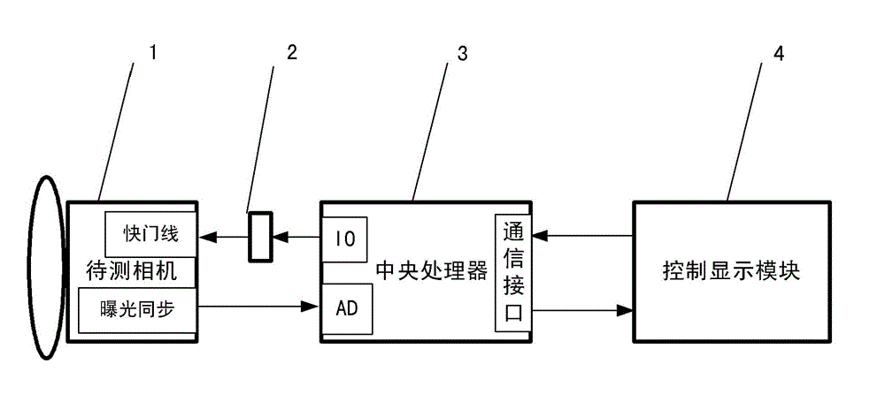
[0018] An improved shutter delay measurement system of the present invention such as image 3 As shown, the system is composed of a camera to be tested 1, a controllable switch 2, a central processing unit 3 and a control display module 4, the central processing unit 3 contains an analog-to-digital converter AD and a counter T, and the controllable switch 2 is located in the camera to be tested 1 between the shutter line and the central processing unit 3, the central processing unit 3 is connected to the control display module 4, the analog-to-digital converter AD is connected to the exposure synchronous signal end of the camera 1 to be tested, and the control display module 4 sends a photographing instruction, and the cen...


PUM


Abstract

The invention relates to an improved shutter delay measurement system which is characterized by comprising a to-be-measured camera, a controllable switch, a central processing unit and a control display module, wherein the central processing unit comprises an analog-to-digital converter and a counter; the controllable switch is positioned between a shutter release of the to-be-measured camera and a central processing unit; the central processing unit is connected with the control display module; the analog-to-digital converter is connected with an exposure synchronous signal end of the to-be-measured camera; the control display module gives a shooting instruction; after receiving the instruction of the control display module, the central processing unit controls the controllable switch to allow the to-be-measured camera to shoot; the counter is started at the moment; a synchronous signal is fed back to the central processing unit after the to-be-measured camera shoots; the counter stops counting at the moment, and transmits a count value to the control display module for processing and displaying; the delay and shutter time of each to-be-measured camera can be measured according to the count value; and the count frequency can be changed by changing a count cycle value of the central processing unit through software, that is the measurement precision of a camera shutter is changed.

Description

technical field [0001] The invention relates to an improved camera shutter delay measurement system, which is applied to multi-camera synchronous exposure control and is suitable for the field of multi-camera large field of view splicing. Background technique [0002] In recent years, with the development of science and technology, the imaging quality of civilian cameras is getting better and better, and the quality is getting lighter and lighter. On the one hand, researchers are developing aerial cameras with independent intellectual property rights, and on the other hand, they directly transform mature civilian cameras. To make it directly applicable to aerial survey and reconnaissance, when a camera with a large field of view is required, it is necessary to combine two or more cameras according to a certain angle. [0003] The exposure delay of civilian cameras is affected by the internal hardware and shooting parameters (shutter speed, F number, ISO, etc.) of a single ca...

Claims


Application Information

Patent Timeline
Patent Type & Authority Applications(China)
IPC IPC(8): G03B43/02
Inventor 汪旋梁伟高晓东
Owner INST OF OPTICS & ELECTRONICS - CHINESE ACAD OF SCI
Learn More