Single-oil passage pre-diaphragm type staggered plate primary combustion stage premixing and pre-vaporizing low-pollution combustor

A technology of combustion chamber and main combustion stage, which is applied in the direction of combustion chamber, continuous combustion chamber, combustion method, etc., to achieve the effect of improving uniformity, reducing pollution emissions and reducing pollution emissions

Active Publication Date: 2013-10-02
BEIHANG UNIV +1
View PDF8 Cites 14 Cited by
  • Summary
  • Abstract
  • Description
  • Claims
  • Application Information

AI Technical Summary

Problems solved by technology

[0003] The technical problem to be solved by the present invention is: to overcome the deficiencies in the prior art and to provide a premixed pre-evaporation low-pollution combustion chamber with a single oil path pre-film interlaced plate main combustion stage by using the pre-mixed pre-evaporation combustion technology, the combustion chamber The mode of central staged combustion is adopted, the pre-combustion stage is in the center, and the combination of diffusion combustion and premixed combustion is adopted to ensure the stability and safety of the combustion chamber, and at the same time reduce pollution emissions under small working conditions; the main combustion The stage adopts premixed pre-evaporation combustion method, which can effectively reduce combustion pollutants

Method used


Image

  • Single-oil passage pre-diaphragm type staggered plate primary combustion stage premixing and pre-vaporizing low-pollution combustor
  • Single-oil passage pre-diaphragm type staggered plate primary combustion stage premixing and pre-vaporizing low-pollution combustor
  • Single-oil passage pre-diaphragm type staggered plate primary combustion stage premixing and pre-vaporizing low-pollution combustor

Examples


Embodiment Construction

[0031] The present invention will be further described below in conjunction with the accompanying drawings and specific embodiments.

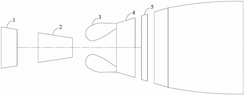
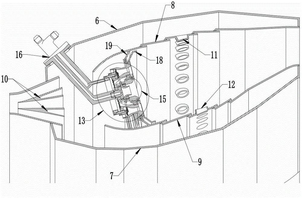
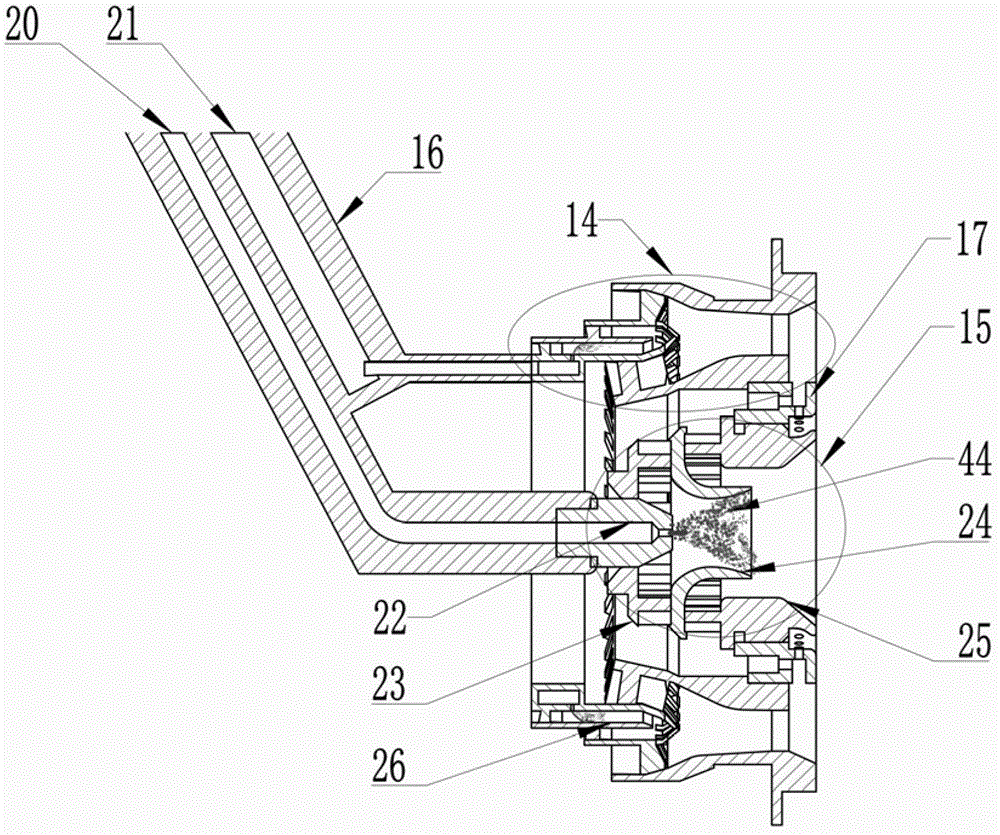
[0032] Figure 1-9 Disclosed is a premixed pre-evaporation low-pollution combustion chamber of a single-oil pre-film type staggered plate main combustion stage. Indoor casing 7, outer wall of flame tube 8, inner wall of flame tube 9 and combustion chamber head 13, diffuser 10 is welded together through inner and outer walls, casing 6 outside combustion chamber and casing 7 inside combustion chamber, outer wall of flame tube 8 The support plate at the rear edge is connected with the casing 6 outside the combustion chamber, and the inner wall 9 of the flame tube is also connected and fixed with the casing 7 inside the combustion chamber through the support plate at the rear; The mixing hole 11 is provided with a mixing hole 12 in the inner ring of the flame tube at the rear of the inner wall 9 of the flame tube. The mixing hole 11 enters the fl...


PUM


Abstract

The invention relates to a single-oil passage pre-diaphragm type staggered plate primary combustion stage premixing and pre-vaporizing low-pollution combustor, which adopts a single-annulus cavity structure, a central staged combustion method is adopted by the combustor, a combustor head is divided into a pre-combustion stage and a primary combustion stage, the combination of diffusion combustion and swirling premixed combustion is adopted by the pre-combustion stage, and while the stability of combustion is guaranteed, pollutant emission under the low working condition is reduced; and a premixing and pre-vaporizing combustion method is adopted by the primary combustion stage, so that the combustion of pollutants can be effectively reduced. The primary combustion stage is a single-stage oil passage, fuel oil can form an oil film on a pre-diaphragm plate, the oil film is atomized, vaporized and mixed with the air under the action of two streams of swirls, the formed oil-air mixture is radially mixed additionally under the function of the staggered plates, uniform oil-air mixture is formed under the swirling effect of an internal swirler and an external swirler, the pre-diaphragm plate can help to enhance the circumferential uniformity of the oil mist, while the radial mixing and diffusion of the oil mist are enhanced by the staggered plates, consequently, uniform oil-air mixture can be formed at the outlet of the primary combustion stage, and the combustion of pollutants can be reduced.

Description

technical field [0001] The invention relates to the technical field of aviation gas turbines, in particular to a premixing, pre-evaporation and low-pollution combustion chamber of a main combustion stage of a single oil channel pre-film interlaced plate. Background technique [0002] The basic performance and structural distribution of modern aero-engine combustors have reached a fairly high level, but there are still a lot of problems and challenges for modern aero-engine combustors. The development and application of new materials, new processes, new structures, and new concepts It is the source to ensure its continuous progress. The main development trend of modern civil aeroengine combustors is low-pollution combustion. Combustion chambers of civil aeroengines must meet increasingly stringent aeroengine pollution emission standards. The currently adopted CAEP6 (Committee on Aviation Environmental Protection) standard has very strict regulations on pollutant emissions, ...

Claims


Application Information

Patent Timeline
IPC IPC(8): F23R3/52F23R3/30F23R3/38
Inventor 王凯许全宏林宇震李林郭凯徐华胜邓远灏
Owner BEIHANG UNIV
Why Eureka
Try Eureka