Biomass spiral-vibration electromagnetic induction pyrolysis reactor and pyrolysis treatment method thereof
A pyrolysis reactor, electromagnetic induction technology, applied in the fields of biofuel, direct heating dry distillation, preparation of liquid hydrocarbon mixtures, etc., can solve the problems of unstable pyrolysis process and easy blockage, and achieve simple structure and convenient operation and control. , Universal effect
- Summary
- Abstract
- Description
- Claims
- Application Information
AI Technical Summary
Problems solved by technology
Method used
Image
Examples
Embodiment 1
[0067]The particle size of corn stalks is 3 mm, and the particle size of quartz sand is 5 mm.
[0068] Utilize the pyrolysis steps of the biomass spiral vibration electromagnetic induction pyrolysis reactor of the present invention as follows:
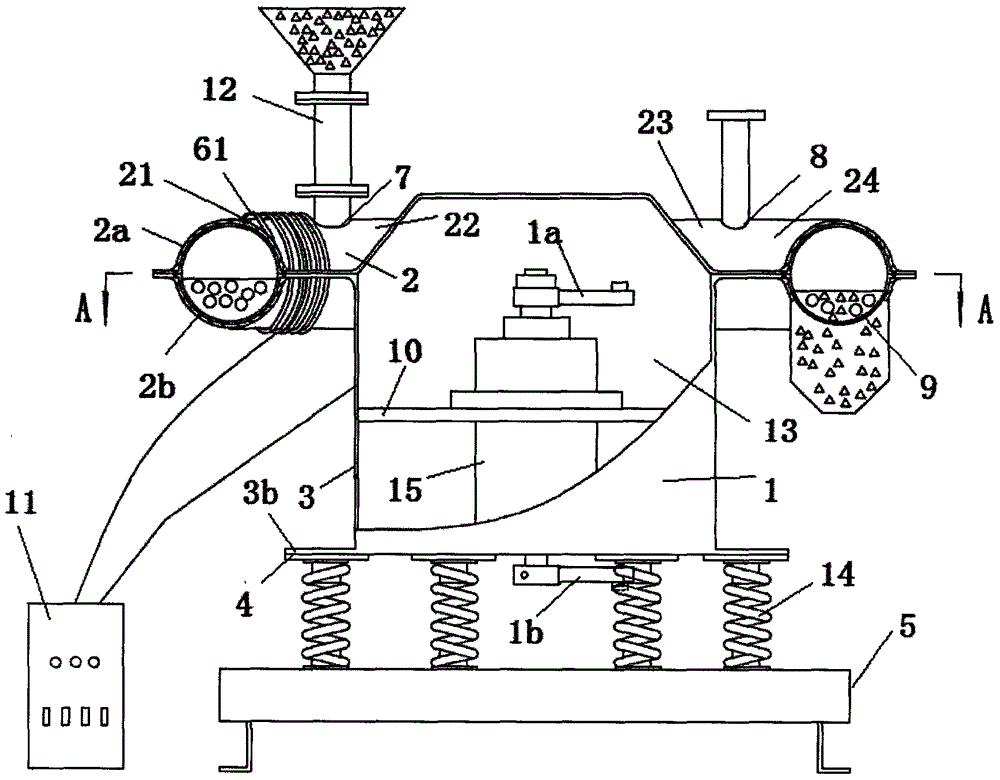
[0069] Quartz sand enters the hollow cylinder 2 from the feed bin 12, starts the vibration motor 15, the induction coil 61 of the preheating part, and the induction coil 62 of the pyrolysis part, and the quartz sand vibrates up and down in the hollow cylinder 2 from the inside to the outside. During the movement, the quartz sand is heated by the wall surface of the preheating cylinder 2, and the heating power of the induction coil 61 of the preheating part and the induction coil 62 of the pyrolysis part are adjusted and controlled. and heating time, keep the cylinder wall temperature of the preheating cylinder 21 to 650°C, and the cylinder wall temperature of the pyrolysis cylinder 23 to 600°C; The straw particles are mixed with the p...
Embodiment 2
[0071] Adjust and control the heating power and heating time of the induction coil 61 of the preheating part and the induction coil 62 of the pyrolysis part, and keep the temperature of the wall surface of the preheating cylinder 21 to 900°C and the temperature of the wall surface of the pyrolysis cylinder 23 to 850°C °C, at this time, the average temperature of the biomass particles in the pyrolysis cylinder 23 is 830°C, adjust the excitation force of the vibration motor 15, adjust the clockwise moving speed of the biomass particles and the heat carrier in the pyrolysis cylinder 23, and control The residence time of biomass particles in the pyrolysis cylinder is 7s, which meets the technical requirements of pyrolysis and gasification of biomass particle materials. Others are the same as embodiment one.
Embodiment 3
[0073] Adjust and control the heating power and heating time of the induction coil 61 of the preheating part and the induction coil 62 of the pyrolysis part, and keep the temperature of the wall surface of the preheating cylinder 21 to 650°C and the temperature of the wall surface of the pyrolysis cylinder 23 to 500°C. °C, at this time, the average temperature of the biomass particles in the pyrolysis cylinder 23 is 450°C, adjust the excitation force of the vibrating motor 15, adjust the clockwise moving speed of the biomass particles and the heat carrier in the pyrolysis cylinder 23, The residence time of biomass particles in the pyrolysis cylinder is controlled to be 8s, which meets the technical requirements of pyrolysis and carbonization of biomass particle materials. Others are the same as embodiment one.
PUM
| Property | Measurement | Unit |
|---|---|---|
| particle diameter | aaaaa | aaaaa |
| particle diameter | aaaaa | aaaaa |
Abstract
Description
Claims
Application Information
 - R&D
- Intellectual Property
- Life Sciences
- Materials
- Tech Scout
- Unparalleled Data Quality
- Higher Quality Content
- 60% Fewer Hallucinations
Browse by: Latest US Patents, China's latest patents, Technical Efficacy Thesaurus, Application Domain, Technology Topic, Popular Technical Reports.
© 2025 PatSnap. All rights reserved.Legal|Privacy policy|Modern Slavery Act Transparency Statement|Sitemap|About US| Contact US: help@patsnap.com


