Switched reluctance motor and control method thereof

A technology of a switched reluctance motor and a control method, applied in the control field of switched reluctance motor and switched reluctance motor, can solve the problems of large torque ripple, application limitation of switched reluctance motor, high noise, etc., to achieve torque ripple Small, low noise, noise reduction effect

Inactive Publication Date: 2013-09-25
GREE ELECTRIC APPLIANCES INC +4
View PDF4 Cites 3 Cited by
  • Summary
  • Abstract
  • Description
  • Claims
  • Application Information

AI Technical Summary

Problems solved by technology

[0007] Since the switched reluctance motor controls the motor through the calculation and comparison of the flux linkage, it still fails to effectively solve the problems of large torque ripple and excessive noise during the operation of the motor, and the application of the switched reluctance motor is still restricted

Method used


Image

  • Switched reluctance motor and control method thereof
  • Switched reluctance motor and control method thereof
  • Switched reluctance motor and control method thereof

Examples


no. 1 example

[0030] The switched reluctance motor in this embodiment is a motor with a double salient pole structure, which has a stator and a rotor. The stator has a stator core and coils wound on the stator core, and each coil is wound on a salient pole. The multiple salient poles on the stator core are evenly arranged in the circumferential direction of the stator core, and the two salient poles facing each other in the radial direction form a pair of salient poles, and the two coils wound on the same pair of salient poles are the same phase coils , the two coils of the same phase coil are connected in series.

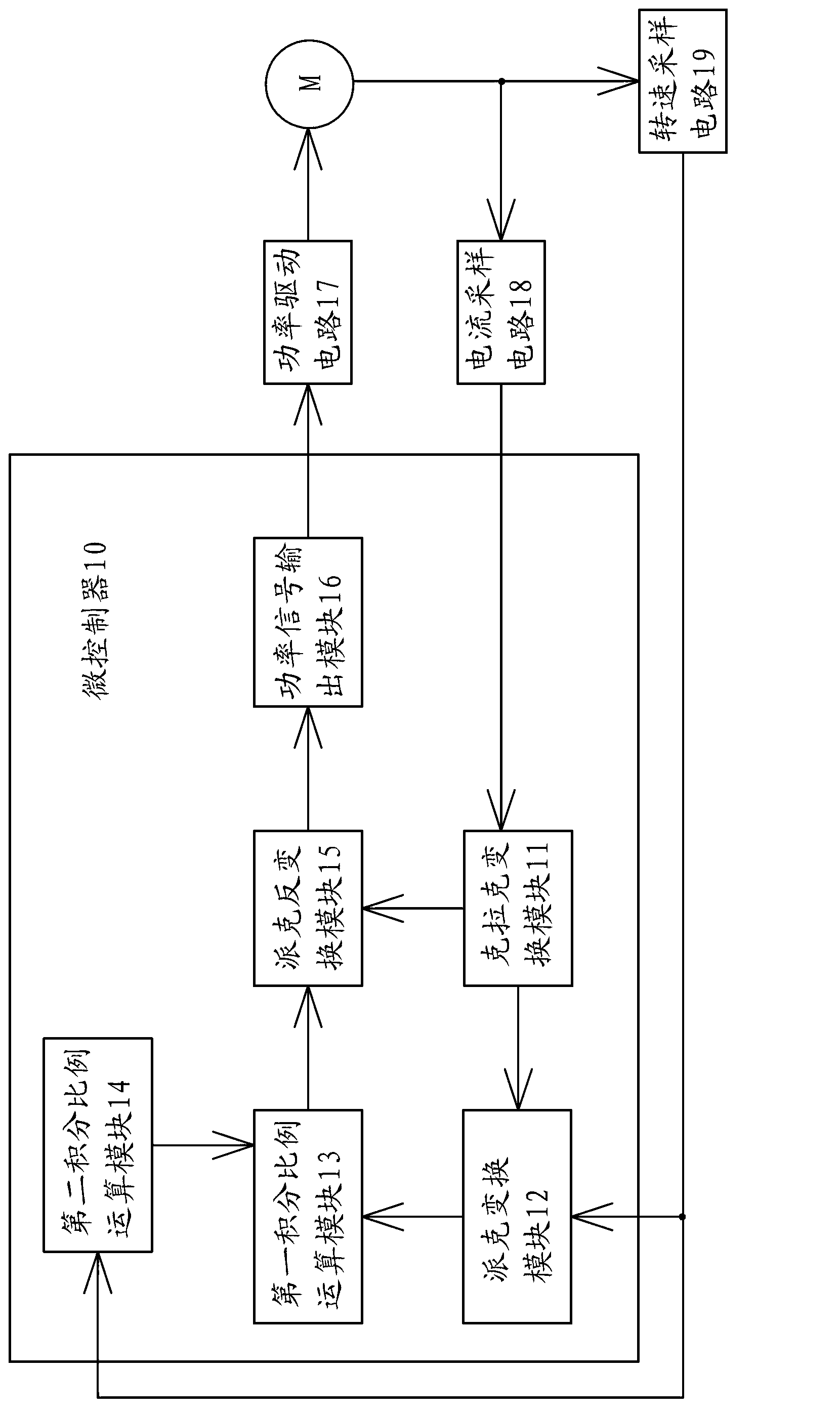
[0031] A switched reluctance motor has a controller for controlling the operation of the motor, such as figure 1 As shown, the controller of this embodiment has a microcontroller 10 , a power drive circuit 17 , a current sampling circuit 18 , and a rotational speed sampling circuit 19 . Microcontroller 10 is the core of controller, and it is single-chip microcomputer, is provid...

no. 2 example

[0093] The switched reluctance motor of this embodiment has a stator and a rotor. The stator has a stator core and a plurality of coils wound on the stator core. Two coils on opposite salient poles are connected in series to form a phase coil. In this embodiment, the number of phases of the coil is n phases.

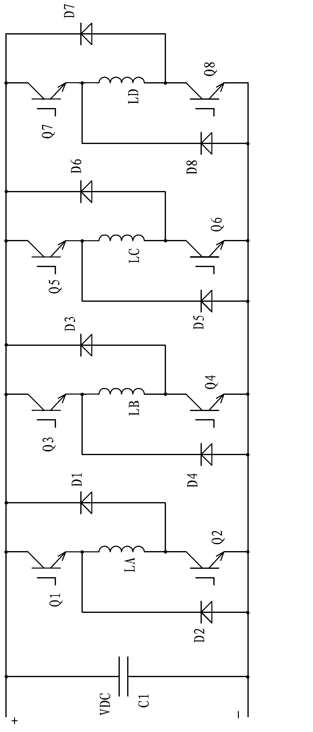
[0094] The switched reluctance motor is also provided with a controller, the controller has a microcontroller, a power drive circuit, a current sampling circuit and a speed sampling circuit, wherein the power drive circuit has n sets of power tubes, and each set of power tubes includes a Two power tubes at both ends of the coil, such as Figure 8 shown.

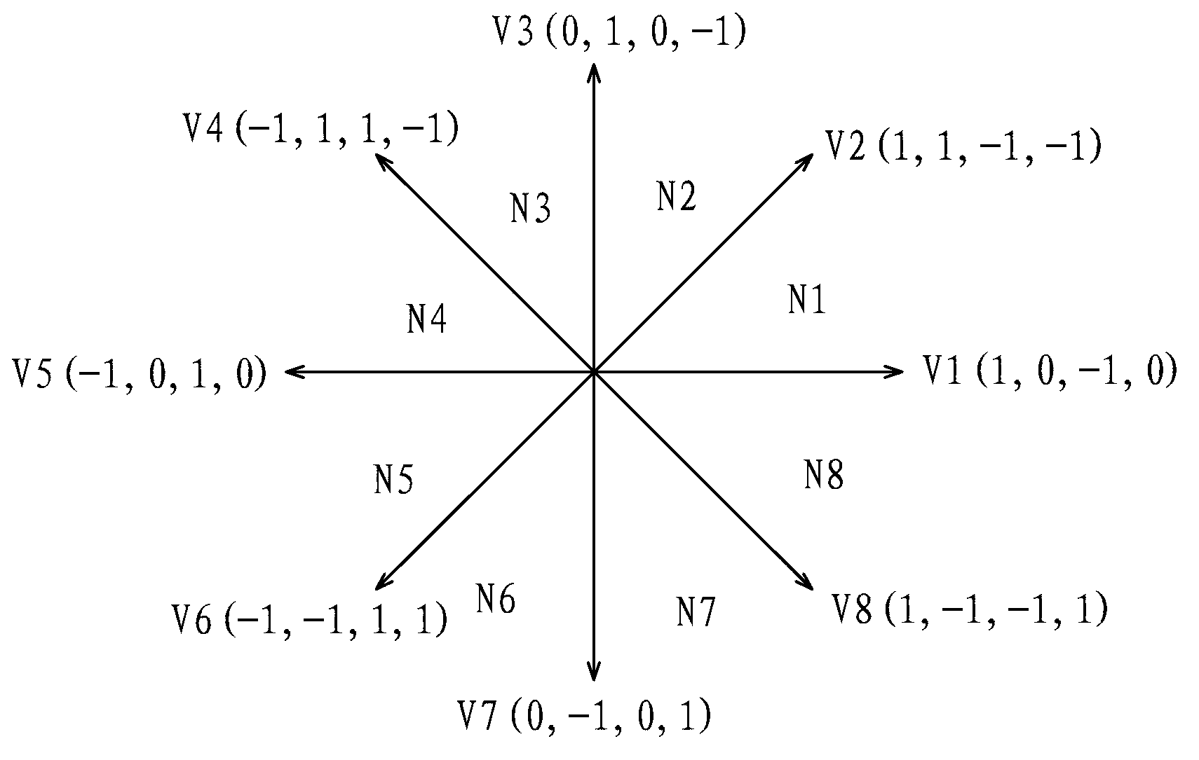
[0095] To control the switched reluctance motor, multiple working states of multiple power transistors are firstly selected. Preferably, the number of selected working states is twice the number of coil phases, so as to facilitate control. And, calculate the voltage vector of the power drive circuit in each working st...


PUM


Abstract

The invention provides a switched reluctance motor and a control method of the switched reluctance motor. The method comprises selecting working states of power tubes, calculating the voltage vector of a power-driven circuit in each working state, dividing a plurality of working sections, sampling current signals flow through a multiphase coil and carrying out clark transformation; sampling rotating speed signals of a rotor of the switched reluctance motor and carrying out Park transformation, and obtaining direct axis current signals and quadrature axis current signals; carrying out integral proportion operation on the direct axis current signals and the quadrature axis current signals to obtain direct axis voltage signals and quadrature axis voltage signals, and carrying out Park inverse transformation on the direct axis voltage signals and the quadrature axis voltage signals; calculating the duty ratio of a pulse width modulation signal loaded on each power tube in each working section based on a volt-second vector method according to the signals after the Park inverse transformation. The switched reluctance motor is provided with a controller, and the controller controls the switched reluctance motor to operate based on the control method of the switched reluctance motor. The switched reluctance motor and the control method of the switched reluctance motor can reduce the torque pulse of the switched reluctance motor and reduces noise generated by the switched reluctance motor.

Description

technical field [0001] The invention relates to the field of motors, in particular to a switched reluctance motor and a control method for the switched reluctance motor. Background technique [0002] The switched reluctance motor has the advantages of compact and firm structure, simple drive circuit, low cost, reliable performance, etc., and also has the characteristics of conveniently realizing four-quadrant control, making it very suitable for various operating conditions of electric vehicles. Motors with great potential in vehicles. [0003] Most switched reluctance motors have a double salient pole structure, that is, both the stator core and the rotor core have salient poles, and only coils are wound on the magnetic poles of the stator core, while neither coils are wound on the magnetic poles of the rotor core. Not a permanent magnet. Usually, the number of salient poles of the stator core is an even number, and the salient poles are uniformly distributed in the circu...

Claims


Application Information

Patent Timeline
IPC IPC(8): H02P21/00
Inventor 平丽王灿赵志丽
Owner GREE ELECTRIC APPLIANCES INC
Why Eureka
Try Eureka