Space vector modulation method for three-level output based on three-level voltage source inverter

A technology of voltage source inverter and space vector modulation, which is applied in the field of multi-level conversion, can solve the problems of complex and cumbersome modulation strategies, complex structures, and unbalanced midpoint potentials, and achieve simplified modulation strategies, simplified topology structures, and reduced The effect of the number of devices

Active Publication Date: 2016-09-14
HARBIN INST OF TECH
View PDF3 Cites 0 Cited by
  • Summary
  • Abstract
  • Description
  • Claims
  • Application Information

AI Technical Summary

Problems solved by technology

[0005] In order to solve the problems of unbalanced midpoint potential and complicated modulation strategy caused by the complex structure of the existing level shifter, the present invention designs a new three-level voltage source inverter topology to realize three-level Output space vector modulation method

Method used


Image

  • Space vector modulation method for three-level output based on three-level voltage source inverter
  • Space vector modulation method for three-level output based on three-level voltage source inverter
  • Space vector modulation method for three-level output based on three-level voltage source inverter

Examples


specific Embodiment approach 1

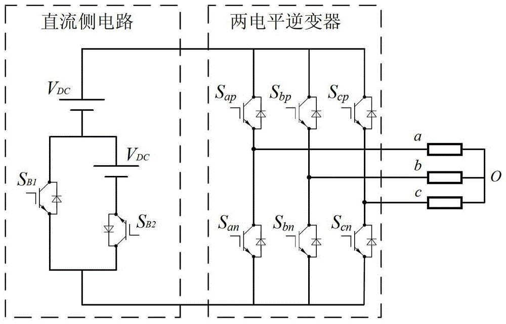
[0021] Specific implementation mode one: see figure 1 This embodiment will be described. The new three-level voltage source inverter described in this embodiment is composed of a DC side circuit and an inverter side circuit, wherein the DC side circuit is used to output DC power to the inverter side circuit, and the inverter side circuit consists of two A level inverter circuit, the two-level inverter circuit converts the input DC signal into a three-level signal for output.

specific Embodiment approach 2

[0022] Embodiment 2: The difference between this embodiment and the novel three-level voltage source inverter described in Embodiment 1 is that the two-level inverter circuit consists of six IGBT switches S ap , S bp , S cp , S an , S bn and S cn composition, the six IGBT switches in the S xn and S xp form a bridge arm, where S xn is the lower bridge arm, S xp is the upper bridge arm, x∈{a,b,c}; the three bridge arms are connected in parallel on the DC output side of the DC side circuit, and the connection point between the upper bridge arm and the lower bridge arm of each bridge arm is a two-level inverter An inverted level output of the circuit.

specific Embodiment approach 3

[0023] Embodiment 3: The difference between this embodiment and the novel three-level voltage source inverter described in Embodiment 1 or 2 is that the DC side circuit consists of two DC sources and two IGBT switches S B1 , S B2 Composed of one DC power supply and one IGBT switch in series, then connected in parallel with another IGBT switch, and then connected in series with another DC power supply.

[0024] In this embodiment, the voltage amplitudes output by the two DC power supplies are both V DC .

[0025] In the novel three-level voltage source inverter of the present invention, the two IGBT switches S located in the DC side circuit B1 , S B2 The switching state of the always remains reversed.

[0026] In the novel three-level voltage source inverter of the present invention, the six IGBT switches S located in the two-level inverter circuit ap , S bp , S cp , S an , S bn and S cn , the two IGBT switch tubes S located in the same bridge arm xp and S xn The sw...


PUM


Abstract

The invention relates to the technical field of multilevel conversion, discloses a novel three-level voltage source inverter and solves the problem that existing level converters are complex in structure and complex to control. A direct-current side circuit is composed of two direct-current power sources and two IGBT (insulated gate bipolar transistor) switches SB1 and SB2, and one of the direct-current power sources is serially connected with one of the IGBT switches to be parallelly connected with the other IGBT switch to be serially connected with the other direct-current power source; an inverter side circuit is a two-level inverter circuit which is composed of six IGBT switches, the Sxn and the Sxp among the six IGBT switches form a bridge arm, the Sxn is a lower bridge arm, the Sxp is an upper bridge arm, and x refers to one of a, b and c; three bridge arms are parallelly connected on a direct-current output side of the direct-current side circuit, and the connection point of the upper bridge arm and the lower bridge arm of each bridge arm serves as one inverter level output end of the two-level inverter circuit. By the novel three-level voltage source inverter, topological structures of three levels are simplified, the number of devices is reduced, and the problem of neutral point potential unbalance of conventional three-level inverters does not exist.

Description

technical field [0001] The invention relates to the technical field of multilevel conversion. Background technique [0002] Multilevel converters have the advantages of low device voltage stress, low total harmonic distortion (THD) of output waveforms, low system electromagnetic interference (EMI), and low loss. Great attention has been paid to the field of fuel cell and AC motor speed regulation. [0003] Existing multilevel converters are divided into three basic types: diode clamp type, flying capacitor type and cascaded type. [0004] As the number of levels increases, the number of clamping devices required doubles or even increases quadratically. In addition to increasing system cost and control complexity, a large number of devices means that the possibility of failure increases. In order to obtain a higher level of output, people usually need a more complex topology, this shortcoming limits the application of multilevel technology, the traditional existing three-le...

Claims


Application Information

Patent Timeline
Patent Type & Authority Patents(China)
IPC IPC(8): H02M7/483
Inventor 刘洪臣卢志国王国立
Owner HARBIN INST OF TECH
Why Eureka
Try Eureka