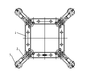
Square frame type damping spacer rod
A technology of spacer bar and square frame, which is applied in the direction of maintaining the distance between parallel conductors, etc., can solve the problems of small overall turning radius, poor strength, and poor stability of the frame, and achieve the advantages of increasing length, improving stability, and improving strength. Effect
Inactive Publication Date: 2013-09-18
YANGZHOU FEIHONG ELECTRIC MATERIAL
View PDF0 Cites 0 Cited by
- Summary
- Abstract
- Description
- Claims
- Application Information
AI Technical Summary
Problems solved by technology
[0002] Damping spacer, as a commonly used power equipment, is widely used on transmission lines. The existing cross-shaped spacer has poor stability and strength, and the overall radius of gyration of the frame is not large, which can no longer meet the requirements of UHV in the power industry. The need for long-distance and large-span transportation development
Method used
View moreImage
Smart ImageViewing Examples
Examples
Embodiment Construction
[0010] The invention includes a cross-shaped spacer bar damping structure, a spliced chuck 3, a rectangular spacer bar frame 1 and a clamp main body 2 fixing structure.
[0011] Its central frame is 8%-9% larger than the national standard size.
[0012] Preferably, the central frame is 8.5% larger than the national standard size.
Login to View More PUM
 Abstract
The invention relates to a damping spacer rod which comprises a cross-shaped spacer rod damping structure, splicing chucks, and a fixation structure of a rectangular spacer rod frame and line clip bodies. According to the invention, the whole structure retains the cross-shaped spacer rod damping structure and the splicing chuck, and absorbs the design structure of the fixation of the rectangular spacer rod frame and the line clip bodies; the strength is greatly improved; the length ratio of the center frame to each line clip body is adjusted; the length of the center frame is increased; the whole gyration radius of the frame part is increased; the whole stability of the spacer rod is improved; and the damping spacer rod plays the roles of subspan oscillation inhibiting and torsion.
Description
technical field [0001] The invention relates to a damping spacer rod, which is used for splitting parallel conductors of 500-1000KV transmission lines in the power industry. Background technique [0002] Damping spacer, as a commonly used electrical equipment, is widely used on transmission lines. The existing cross-shaped spacer has poor stability and strength, and the overall radius of gyration of the frame is not large, which can no longer meet the UHV requirements of the power industry. The needs of long-distance and large-span transportation development. Contents of the invention [0003] The purpose of the present invention is to provide a square frame type damping spacer rod with good stability and good performance in view of the above defects. [0004] For this reason, the technical solution adopted by the present invention is: the present invention includes a cross-shaped spacer bar damping structure and a spliced chuck, a rectangular spacer bar frame and a cla...
Claims
Login to View More Application Information
Patent Timeline
 Patent Type & Authority Applications(China)
IPC IPC(8): H02G7/12
Inventor 王霖
Owner YANGZHOU FEIHONG ELECTRIC MATERIAL
Features
- R&D
- Intellectual Property
- Life Sciences
- Materials
- Tech Scout
- Unparalleled Data Quality
- Higher Quality Content
- 60% Fewer Hallucinations
Learn More Browse by: Latest US Patents, China's latest patents, Technical Efficacy Thesaurus, Application Domain, Technology Topic, Popular Technical Reports.
© 2025 PatSnap. All rights reserved.Legal|Privacy policy|Modern Slavery Act Transparency Statement|Sitemap|About US| Contact US: help@patsnap.com

