Eureka AIR delivers breakthrough ideas for toughest innovation challenges, trusted by R&D personnel around the world.

Fractal ultra-wideband trap antenna with C band suppression function

A notch antenna and C-band technology, which is applied in the field of fractal ultra-wideband notch antenna, can solve the problems of not being able to accurately suppress frequency bands, very little research on band-stop performance, and blind antenna notch frequency bands, etc., and achieve simple structure and low cost. The effect of integrating and suppressing interference frequency bands

Active Publication Date: 2013-09-18
XIAMEN UNIV
View PDF4 Cites 11 Cited by
  • Summary
  • Abstract
  • Description
  • Claims
  • Application Information

AI Technical Summary

Problems solved by technology

[0004] The research on ultra-wideband antennas has achieved many results, and its technology is relatively mature, but there is still room for further improvement in the research on the band-stop performance and structure of ultra-wide-band antennas. In the C-band communication system (3.7-4.2GHz) band-stop There are very few performance studies, and the notch frequency band of the antenna is relatively blind, and it cannot accurately suppress unnecessary frequency bands, which affects the use of other frequency bands

Method used


Image

  • Fractal ultra-wideband trap antenna with C band suppression function
  • Fractal ultra-wideband trap antenna with C band suppression function
  • Fractal ultra-wideband trap antenna with C band suppression function

Examples


Embodiment Construction

[0026] The present invention will be further described below in conjunction with the embodiments and drawings.

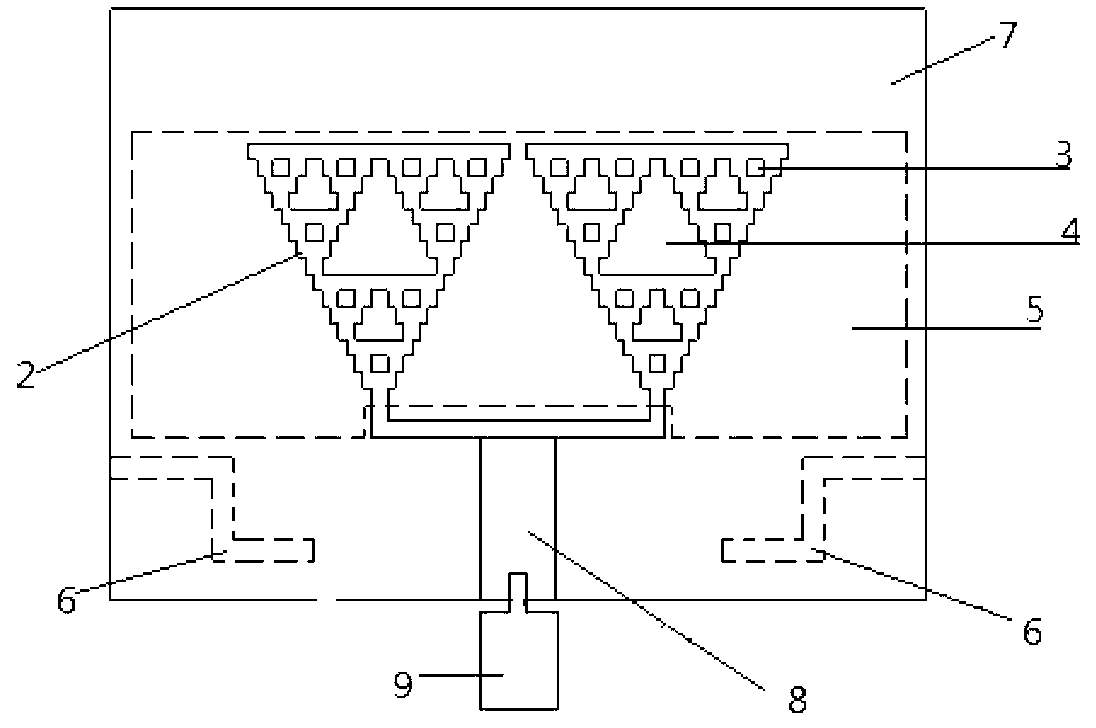
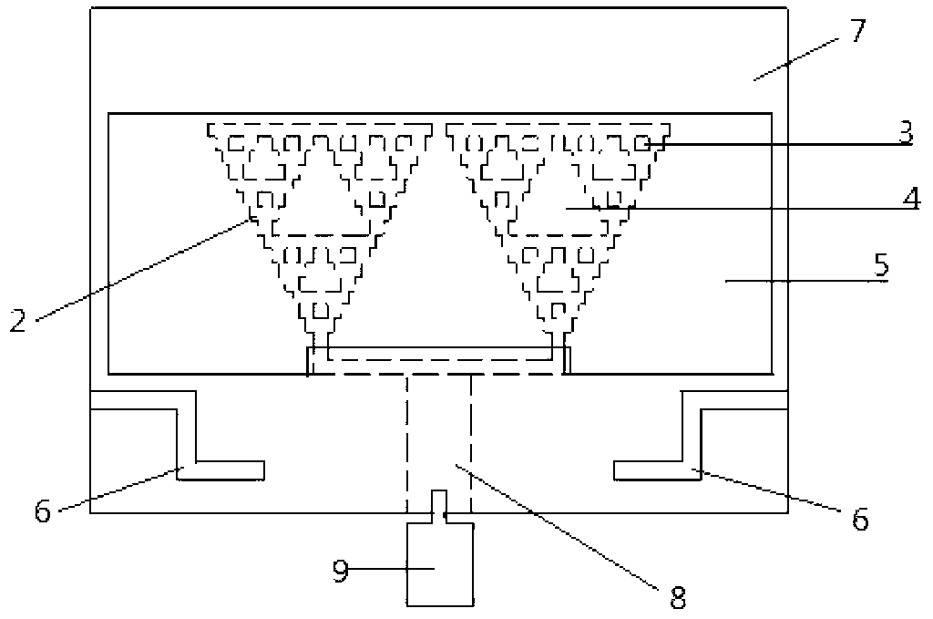
[0027] See figure 1 with 2 , figure 1 Mark 1 in the middle is a dielectric substrate with a dielectric constant of 3.2 and a tangent loss of 0.002, with a length of 40mm, a width of 29mm, and a height of 1.5mm. The upper and lower sides of the dielectric substrate are covered with copper layers, and the upper surface is a T-shaped patch composed of a straight patch and two square patches, and the copper-clad layer 2 of the three-stage improved Sierpinski array structure patch, of which the T-shaped patch The horizontal and vertical widths are 0.8±0.2mm and 3.6±0.6mm, respectively. The horizontal and vertical lengths are 14±2mm and 8±1mm, respectively. The side length of the square patch with symmetrical two ends of the T-shaped patch is 0.8 ±0.2mm, the side length of the third-order improved Sierpinski array structure patch connected to the square patch is 12.5±2.5mm, ...


PUM


Abstract

The invention discloses a fractal ultra-wideband trap antenna with a C band suppression function, and relates to an ultra-wideband antenna. The fractal ultra-wideband trap antenna is provided with a substrate and an SMA (Sub-Miniature-A) joint, wherein an upper surface conductor layer is coated on the upper surface of the substrate; a lower surface conductor layer is coated on the lower surface of the substrate; a planar dipole array which is arranged on the upper surface conductor layer is provided with a high-order improved Sierpinski array structure; a micro-strip line feed part which is arranged on the upper surface conductor layer is used for providing main radiation feed for the planar dipole array; an undercut gap which is arranged on the lower surface conductor layer produces electromagnetic coupling with the planar dipole array to increase the bandwidth; a band suppression gap which is arranged on the lower surface conductor layer is symmetric Z-shaped for intercepting electric wave of a specific frequency radiated by the upper surface conductor layer to form a trap band required by a user; and the SMA joint is connected with the upper surface conductor layer and the lower surface conductor layer on the substrate. The fractal ultra-wideband trap antenna has the advantages of moderate size, large impedance bandwidth, low return loss, high gain, capability of effectively suppressing C band and simple structure and can be used inan ultra-wideband communication system.

Description

Technical field [0001] The invention relates to an ultra-wideband antenna, in particular to a fractal ultra-wideband trap antenna with a C-band suppression function suitable for a C-band ultra-wideband communication system. Background technique [0002] As a transmission technology widely used in remote sensing and radar, in recent years, Ultra-wideband (UWB) technology has received great attention from the wireless communication industry. Ultra-wideband antennas have GHz-level bandwidth, and voice and data communications will likely bring a whole new way. The main advantages of UWB are extremely wide bandwidth, high transmission rate, good confidentiality, strong anti-interference ability, low energy consumption, etc. It has important theoretical value and broad application prospects in many fields such as military, communications, and radar systems. . It will become a technical means to solve the contradiction between the high-speed Internet access requirements of enterprises...

Claims


Application Information

Patent Timeline
IPC IPC(8): H01Q1/38H01Q1/50H01Q1/52H01Q21/00
Inventor 游佰强迟语寒黄天赠周建华
Owner XIAMEN UNIV
Why Eureka
Eureka Blog
Learn More