
Microstrip feed four-notch ultra-wideband antenna structure

An ultra-broadband antenna and microstrip feeding technology, which is applied in the direction of antenna grounding switch structure connection, antenna, antenna grounding device, etc., can solve the problem of increasing antenna size, cost and complexity, high manufacturing precision of notch antenna, and trap antenna Poor adaptability and other issues, to achieve the effect of compact structure, low manufacturing difficulty, and low manufacturing precision requirements

Pending Publication Date: 2020-04-07
GUIZHOU MINZU UNIV
View PDF4 Cites 0 Cited by
  • Summary
  • Abstract
  • Description
  • Claims
  • Application Information

AI Technical Summary

Problems solved by technology

[0002] In recent years, research on ultra-wideband (Ultra-Wideband) antennas has attracted more and more attention, especially after the FCC specified the 3.1-10.6GHz frequency band as a civilian frequency band in 2002, and developed ultra-wideband antennas for this frequency band. Then there is a phenomenon of overlap with some existing frequency bands, such as narrowband signals such as the uplink frequency and downlink frequency of the WiMAX band, the downlink frequency of the INSAT band, and the downlink frequency of the WLAN band. These narrowband signals will cause electromagnetic interference to the ultra-wideband communication system. To eliminate These interferences are usually suppressed by band-rejection filters or notch antennas, but the use of band-rejection devices can increase the size, cost and complexity of the antenna; There will be strong coupling between the notch structures, that is, after adjusting one of the notch frequencies, the other notch frequencies will also change, resulting in very poor adaptability of the notch antenna. A notch antenna structure can only correspond to a narrow band of a specific frequency signal, to change one of the frequencies of the notch antenna, the structure of the entire notch antenna needs to be redesigned. In addition, this also leads to extremely high requirements for the manufacturing accuracy of the notch antenna. As long as there is a notch filter in the notch antenna If the size is out of tolerance, it will affect the whole body, causing the entire notch antenna to be completely scrapped

Method used


Image

  • Microstrip feed four-notch ultra-wideband antenna structure
  • Microstrip feed four-notch ultra-wideband antenna structure
  • Microstrip feed four-notch ultra-wideband antenna structure

Examples


Embodiment 1

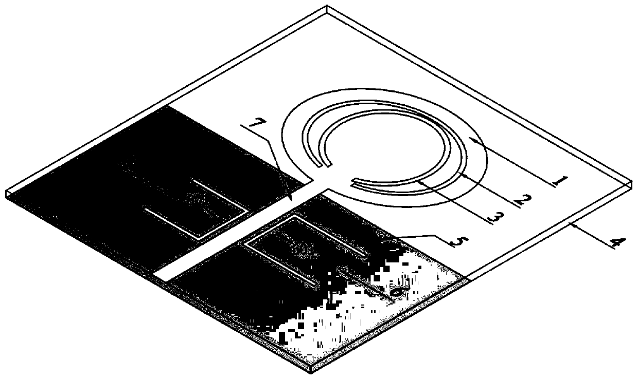
[0041] Implementation Example 1: Reference figure 1 , a four-notch ultra-wideband antenna structure fed by microstrip, comprising: a dielectric substrate 4; a metal ground plane 5, the metal ground plane 5 covering the lower surface of the dielectric substrate 4; a radiation patch 1, the radiation patch The sheet 1 covers the upper surface of the dielectric substrate 4. The radiation patch 1 is left-right symmetrical with the vertical central axis of the dielectric substrate 4 as the central axis. The material of the radiation patch 1 is metal, and a first arc-shaped open loop is opened inside the radiation patch 1. Resonator 2, the radiation patch 1 in the first arc-shaped open-loop resonator 2 is provided with a second arc-shaped open-loop resonator 3; a microstrip feeder 7, the microstrip feeder 7 is covered on the upper surface of the dielectric substrate 4 , the upper end of the microstrip feeder 7 is electrically connected to the radiation patch 1, the central axis of th...


PUM

PropertyMeasurementUnit
lengthaaaaaaaaaa
thicknessaaaaaaaaaa
widthaaaaaaaaaa

Abstract

The invention discloses a microstrip feed four-notch ultra-wideband antenna structure. A first arc-shaped open-loop resonator and a second arc-shaped open-loop resonator are different in shape; the length of a first type U-shaped parasitic band connecting arm is 6.5 mm; the length of a second type U-shaped parasitic band connecting arm is 6.6 mm; the distance between the first U-shaped parasitic band and the lower edge of the dielectric substrate is 6.5 mm, and the distance between the second U-shaped parasitic band and the lower edge of the dielectric substrate is 8.9 mm. The invention aims to solve the problem that strong coupling exists among all notch structures of a four-notch antenna in the prior art.

Description

technical field [0001] The invention relates to the field of radio technology, in particular to a microstrip-fed four-notch ultra-wideband antenna structure. Background technique [0002] In recent years, research on ultra-wideband (Ultra-Wideband) antennas has attracted more and more attention, especially after the FCC specified the 3.1-10.6GHz frequency band as a civilian frequency band in 2002, and developed ultra-wideband antennas for this frequency band. Then there is a phenomenon of overlap with some existing frequency bands, such as narrowband signals such as the uplink frequency and downlink frequency of the WiMAX band, the downlink frequency of the INSAT band, and the downlink frequency of the WLAN band. These narrowband signals will cause electromagnetic interference to the ultra-wideband communication system. To eliminate These interferences are usually suppressed by band-rejection filters or notch antennas, but the use of band-rejection devices can increase the s...

Claims


Application Information

Patent Timeline
Patent Type & Authority Applications(China)
IPC IPC(8): H01Q1/38H01Q1/48H01Q1/50H01Q5/10H01Q5/25H01Q5/307H01P7/08
CPCH01Q1/38H01Q1/48H01Q1/50H01Q5/10H01Q5/25H01Q5/307H01P7/082Y02D30/70
Inventor 王代强罗双王新峰李伟民陈红李烨君蔡勋明
Owner GUIZHOU MINZU UNIV
Learn More