Infrared imaging system and correction method

An infrared imaging system and an infrared radiation technology are applied in the field of infrared focal plane array detector units, which can solve the problems of the adverse impact of the cost of the detector using the system, the inability to solve the limitation of the output dynamic range of the non-uniform focal plane array, and the like. Signal uniformity, simplifying circuit design, reducing the effect of digital-analog interference

Active Publication Date: 2015-08-05
ZHEJIANG DALI TECH
View PDF5 Cites 2 Cited by
  • Summary
  • Abstract
  • Description
  • Claims
  • Application Information

AI Technical Summary

Problems solved by technology

However, since these back-end corrections are processed on the signals that have been amplified and output and sampled by A / D, the correction effect undoubtedly has certain limitations, and it will have a negative impact on the use of detectors and system costs
Also, correction after the detector output cannot resolve the limitation of the dynamic range of the non-uniform focal plane array output

Method used


Image

  • Infrared imaging system and correction method
  • Infrared imaging system and correction method
  • Infrared imaging system and correction method

Examples


Embodiment Construction

[0035] In order to make the object, technical solution and advantages of the present invention more clear, the present invention will be further described in detail below in conjunction with the accompanying drawings and embodiments. It should be understood that the specific embodiments described here are only used to explain the present invention, not to limit the present invention.

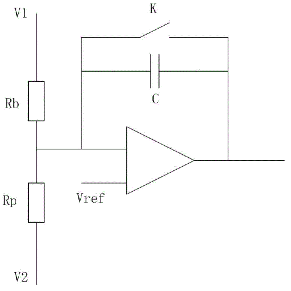
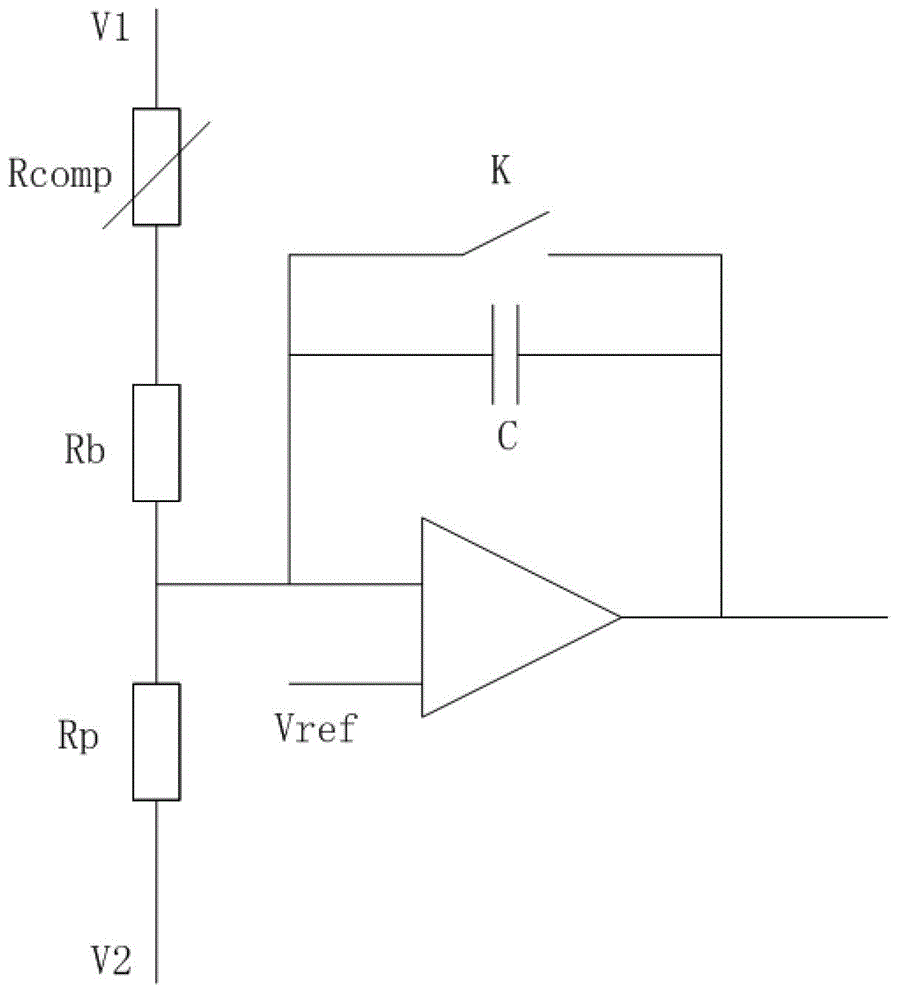
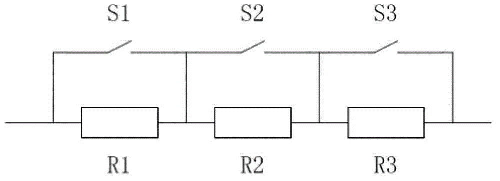
[0036] Aiming at the problems in the prior art, the present invention proposes to design and manufacture blind elements for compensation (hereinafter referred to as compensation blind elements) and corresponding circuit control functions in the focal plane array, in the integral amplifier (for example, capacitive transimpedance amplifier, Before CTIA) integral amplification, each pixel is individually compensated and corrected to effectively improve the signal uniformity of the focal plane array after integral amplification.

[0037] figure 2 It is a schematic diagram of the infrared focal pla...


PUM


Abstract

The invention discloses an infrared focal plane array detector unit with a non-uniform correction function, an infrared imaging system and a non-uniform correction method thereof. The infrared focal plane array detector unit comprises a pixel and a blind pixel which are made of the same thermistor material; the pixel responds to incident infrared radiation, while the blind pixel does not respond to the incident infrared radiation; the pixel and the blind pixel are connected in series, and are electrically connected with the inverted input end of an integrated amplifier, and the other end of the blind pixel, which is opposite to the end electrically connected with the pixel, is electrically connected with a compensating blind pixel; like the blind pixel, the compensating pixel does not respond to the incident infrared radiation; and the compensating pixel is used for compensating the blind pixel and indirectly compensating and correcting the nonuniformity of the corresponding pixel. The invention can effectively compensate the nonuniformity of the resistance of the pixel, thus broadening the dynamic range of the effective output of a focal plane array and decreasing noise-equivalent temperature difference.

Description

technical field [0001] The invention relates to the field of infrared detectors, in particular to an infrared focal plane array detector unit, an infrared imaging system and a non-uniformity correction method thereof. Background technique [0002] Infrared detector technology (especially uncooled infrared detector technology) has been developed rapidly in the past ten years. On the one hand, the uncooled focal plane technology has developed from the initial medium and small scale to large-scale 640×480 arrays, and even 1024×1024 uncooled focal plane arrays. On the other hand, the pixel size is gradually reduced from 50 μm, 35 μm, and 25 μm to 17 μm or below. Due to its advantages of small size, low cost, and good reliability, uncooled focal plane detectors are widely used in many key fields such as industry, electric power, medical treatment, and fire protection. With the improvement of the circuit level and manufacturing process, the sensitivity of the uncooled focal plan...

Claims


Application Information

Patent Timeline
Patent Type & Authority Patents(China)
IPC IPC(8): G01J5/22G01J5/06
Inventor 刘海涛姜利军刘翔尹茂林马志刚
Owner ZHEJIANG DALI TECH
Why Eureka
Try Eureka