
Novel reinforcement device for reinforced concrete beam and floor slab and construction method thereof

A technology for reinforced concrete beams and reinforcement devices, applied in bridge reinforcement, bridges, bridge maintenance, etc., can solve problems such as stress hysteresis effect, anchorage end stripping damage, and restrict the use of reinforcement, so as to avoid stress hysteresis effect and ensure reinforcement effect , Improve the effect of shear strength

Inactive Publication Date: 2013-09-18
HUAQIAO UNIVERSITY +1
View PDF6 Cites 7 Cited by
  • Summary
  • Abstract
  • Description
  • Claims
  • Application Information

AI Technical Summary

Problems solved by technology

These traditional reinforcement methods generally have the following problems: (1) The problem of stress hysteresis effect makes the reinforcement material and the original components work poorly, which greatly affects the reinforcement effect
(2) Due to the existence of the floor, the anchorage length of the reinforcement material is often insufficient, and the peeling damage of the anchorage end is prone to occur
(3) The traditional reinforcement method cannot change the stress state of the original structure, and the internal damage and defects such as cracks in the components cannot be bridged or reduced. If no prestress is applied, the reinforcement material will not be able to play a role in the existing cracks, which will greatly affect Its reinforcement effect restricts its use in reinforcement of damaged components

Method used


Image

  • Novel reinforcement device for reinforced concrete beam and floor slab and construction method thereof
  • Novel reinforcement device for reinforced concrete beam and floor slab and construction method thereof
  • Novel reinforcement device for reinforced concrete beam and floor slab and construction method thereof

Examples


Embodiment Construction

[0033] In order to further explain the technical solutions of the present invention, specific examples are given below to illustrate in detail.

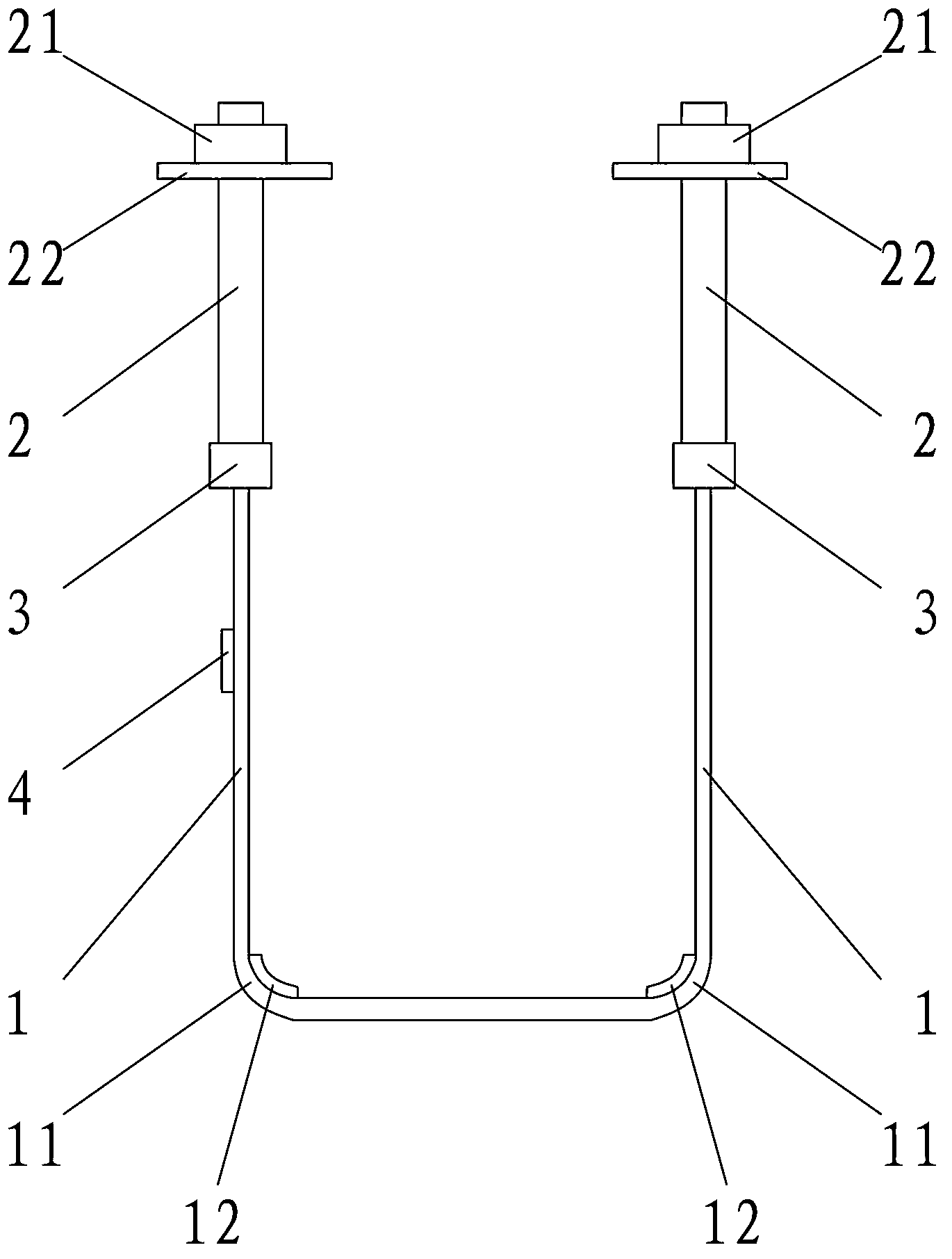
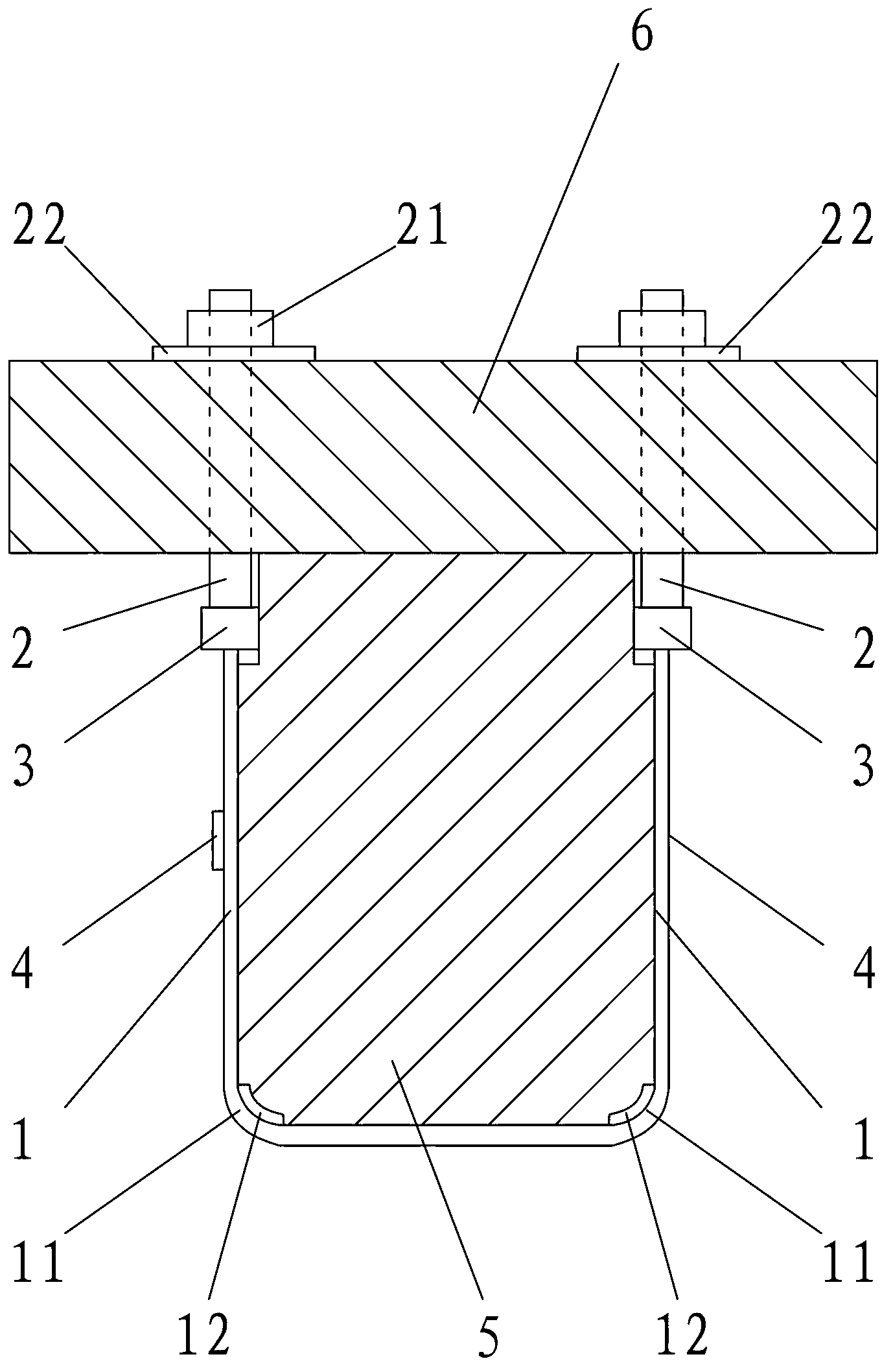
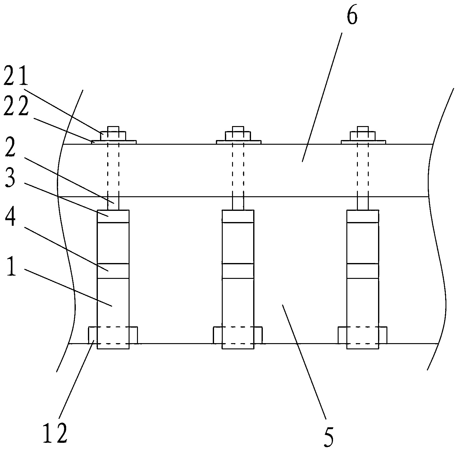
[0034] A novel reinforcing device for reinforced concrete beams and floor slabs of the present invention, such as Figure 1-3 As shown, it includes a hoop part 1 and two bolt parts 2.

[0035] The steel hoop part 1 is U-shaped, tightening the reinforced concrete beam 5 from bottom to top, two bolt parts 2 pass through the floor 6 and are fixedly connected with both ends of the steel hoop part 1, and the nuts 21 of the bolt part 2 are tightened on the The bolt part 2 is exposed above the floor 6. By tightening the bolt part 2, the prestressed tension of the hoop part 1 is realized, and the transverse prestress is applied to the reinforced concrete beam 5, and the reinforced concrete beam 5 and the floor 6 are tightly fastened. Hoop together to realize the shear reinforcement of the reinforced concrete beam 5.

[0036] Preferably, th...


PUM


Abstract

The invention provides a novel reinforcement device for a reinforced concrete beam and a floor slab, which comprises an U-shaped steel hoop part tightening the reinforced concrete beam from bottom to top, and two bolt parts respectively penetrating the floor slab to be fixedly connected with two ends of the steel hoop part, wherein nuts of the bolt parts, which are screwed on the bolt parts, are positioned above the floor slab. Due to the adoption of the technical scheme, the reinforced concrete beam and the floor slab are pre-tightened and locked together through matching of the steel hoop parts and the bolt parts. Compared with the prior art, stress hysteresis effect caused by a traditional reinforcement device can be effectively avoided, the anchoring validity is maintained, the reinforcement effect is effectively ensured, and the shear strength of the reinforced concrete beam is improved. Moreover, the structure is easy to realize, the appearance is compact and beautiful, and the comprehensive practicability is strong. The invention further provides a construction method of the novel reinforcement device, the steps are concise and clear, and the implementation efficiency of the novel reinforcement device can be effectively improved.

Description

technical field [0001] The invention relates to the technical field of building reinforcement, in particular to a novel reinforcement device for reinforced concrete beams and floor slabs and a construction method thereof. Background technique [0002] In engineering structures, it is often necessary to reinforce existing buildings due to factors such as building aging, changes in use functions, structural design or construction errors, and increased fortification standards. The shear reinforcement of reinforced concrete beams is an important part of building reinforcement. There are many shear strengthening methods for reinforced concrete beams, and the commonly used strengthening methods include enlarging section method, pasting fiber reinforced composite material reinforcement method, bonding steel reinforcement method and steel strand polymer mortar reinforcement method, etc. These traditional reinforcement methods generally have the following problems: (1) The problem o...

Claims


Application Information

Patent Timeline
Patent Type & Authority Applications(China)
IPC IPC(8): E01D22/00E04G23/02
Inventor 黄群贤郭子雄陈建华陈昆明洪毅
Owner HUAQIAO UNIVERSITY
Learn More