knife holder

A tool holder and cutting tool technology, applied in the field of road milling machine or similar machine tool holder, surface mining machine, can solve the problems of tool holder wear, cost, breakage, etc., to achieve the effect of cutting

Active Publication Date: 2016-05-04
WIRTGEN GMBH
View PDF8 Cites 0 Cited by
  • Summary
  • Abstract
  • Description
  • Claims
  • Application Information

AI Technical Summary

Problems solved by technology

The tool holder then suffers unprotected wear and cannot accommodate a replacement chisel after a short time
Then, it is necessary to spend a lot of money to replace the tool holder
In addition, if the base part is worn, it must also be separated from the milling roller tube and replaced, with much greater expense and time
[0005] If the state of wear of the chisel is not known in time, or breakage occurs, this can result in high tool costs and machine downtime
This downtime is very costly, so keep it to a minimum

Method used


Image

  • knife holder
  • knife holder
  • knife holder

Examples


Embodiment Construction

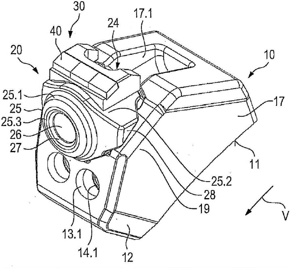
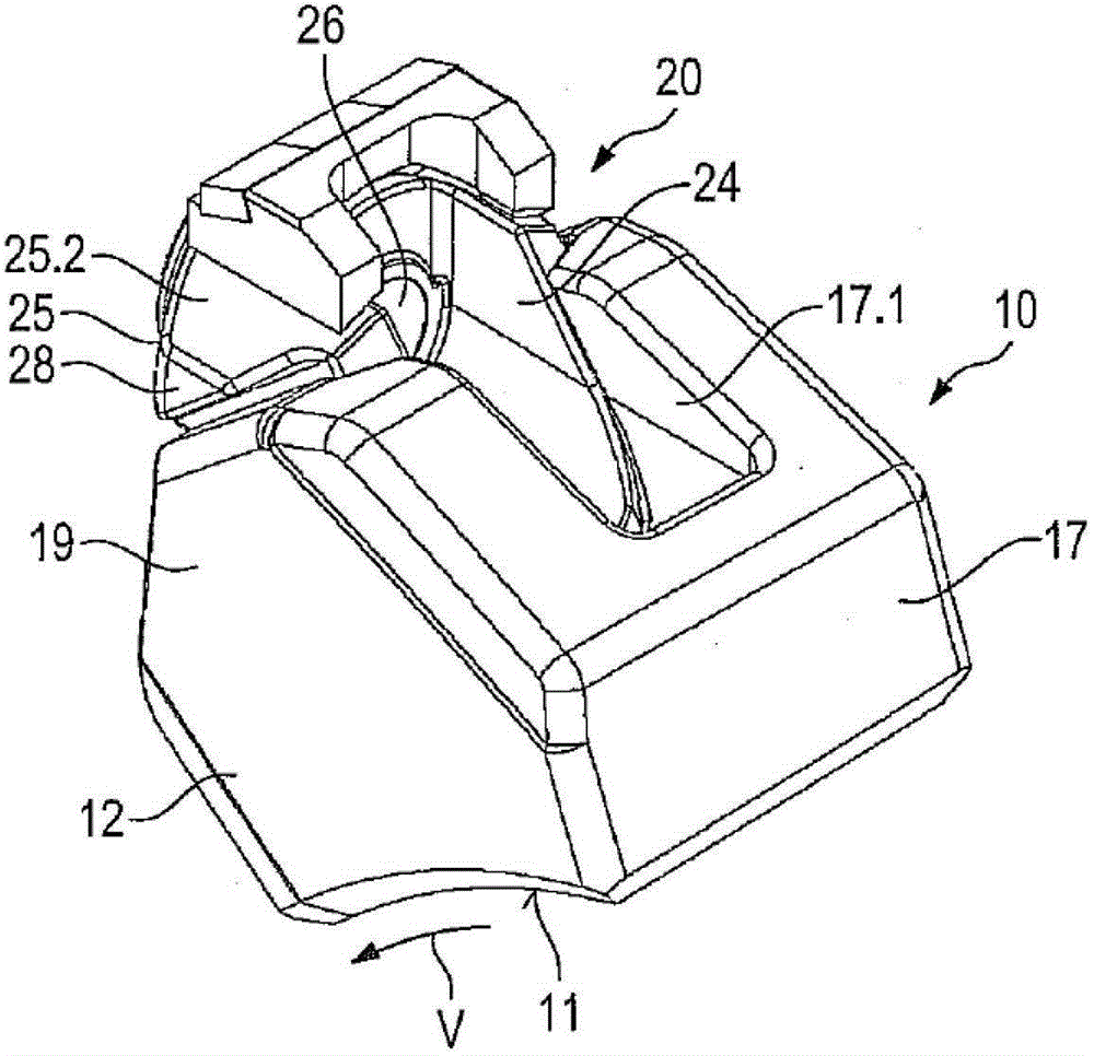
[0037] figure 1Base part 10 is shown with an underside 11 having a concavely arched seating surface. By means of this mounting surface, the base part can be placed on the cylindrical outer surface of the milling roller and fixedly welded thereto. The tool holder 20 is connected to the base part 10 .

[0038] Such as Figure 5 As shown, the base part 10 has a plug receptacle 15 which accommodates the plug-in projection 21 of the tool holder 20 . Refer below Figure 6 to Figure 8 The structure of the tool holder 20 is explained in detail.

[0039] Such as Image 6 As shown, the tool holder 20 has an insertion projection 21 to which a support projection 25 is attached at an angle. In this case, an obtuse angle is ideally enclosed between the insertion projection 21 and the support projection 25 . The insertion projection 21 forms a front side 21 . 1 in the region of its insertion projection front side 22 facing the tool feed direction V. The two grooves are formed in the ...


PUM


Abstract

The invention relates to a tool holder for ground working machines, in particular for surface mining machines, road milling machines or similar machines, which has a support projection with a chisel holder and / or carries a cutting elements. In order to improve the operating stability of the ground working machine, it is provided according to the invention that the bearing projection has or bears a wear protection element with hard Material elements for anti-friction properties.

Description

technical field [0001] The invention relates to a tool holder for a ground working machine, in particular a surface mining machine, a road milling machine or the like, which has a support projection with a chisel receptacle and / or carries a cutting element. [0002] The invention also relates to a support for a tool holder and to a mining machine or similar ground working machine. Background technique [0003] A tool holder changing system with a base part and a tool holder is known from DE 43 22 401 A1. The base part has support feet by means of which the base part can be welded to the outer circumference of the milling roller. The plug receptacle is formed in the base part. The tool holder with its insertion projection can be accommodated in this plug receptacle. To secure the tool holder in the base part, a compression screw is used, which pulls the insertion projection into the plug receptacle and tightens it there. The tool holder has a bore as a chisel holder. A ...

Claims


Application Information

Patent Timeline
Patent Type & Authority Patents(China)
IPC IPC(8): E01C23/088E21C35/19E21C35/193E21C25/10
CPCE21C35/183E21C35/1833E21C35/1831E21C25/10E21C35/18B28D1/186E01C23/088
Inventor 托马斯·莱纳特K·布尔西鲁斯·巴里马尼京特·亨
Owner WIRTGEN GMBH
Why Eureka
Try Eureka