Loading valve for hydraulic part test bench

A technology for test benches and hydraulic parts, which is applied to valve devices, engine components, cocks including cut-off devices, etc. It can solve the problems of high oil sensitivity, low control accuracy, and unstable pressure, and achieve high control accuracy and small size. , good pressure stability

Inactive Publication Date: 2013-09-04
HEFEI AUTOMOBILE OIL PUMP
View PDF6 Cites 0 Cited by
  • Summary
  • Abstract
  • Description
  • Claims
  • Application Information

AI Technical Summary

Problems solved by technology

In the prior art, the hydraulic loading devices used in the hydraulic parts testing test bench mainly include: using electromagnetic proportional valves for loading, high cost, unstable pressure, low control accuracy, poor stability, high sensitivity to oil pollution, and prone to oil leakage and stagnation , Difficult to maintain and other problems; by increasing the output load, such as the load of the oil cylinder, the structure is complex, difficult to operate and the cost is high

Method used


Image

  • Loading valve for hydraulic part test bench
  • Loading valve for hydraulic part test bench
  • Loading valve for hydraulic part test bench

Examples


Embodiment Construction

[0018] The embodiments of the present invention are described in detail below. This embodiment is implemented on the premise of the technical solution of the present invention, and detailed implementation methods and specific operating procedures are provided, but the protection scope of the present invention is not limited to the following implementation example.

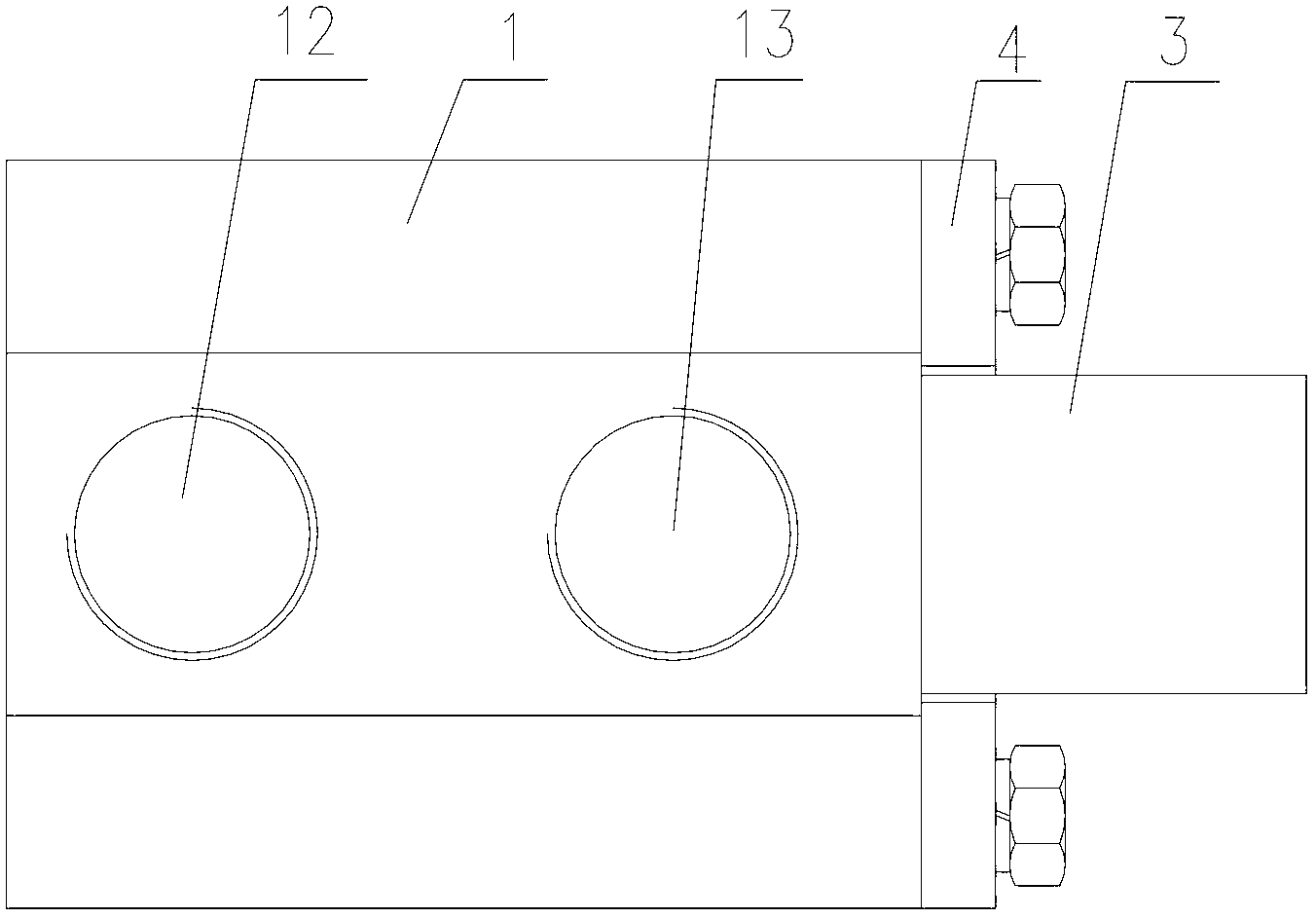
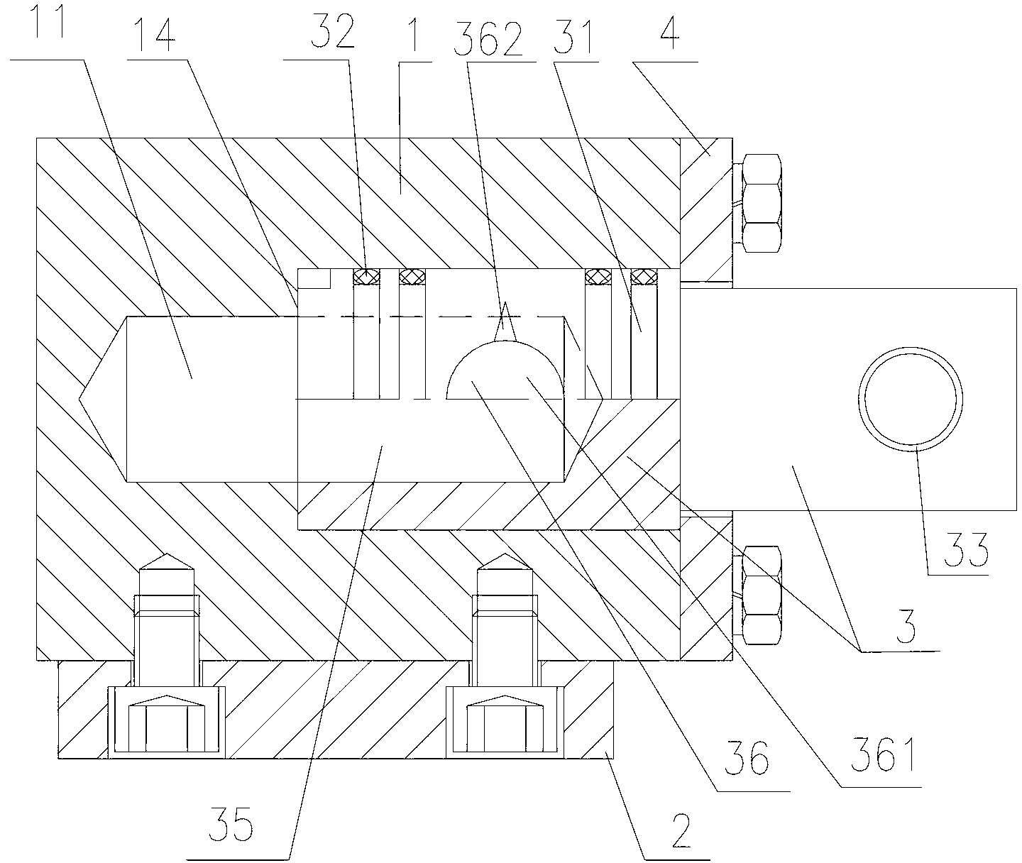
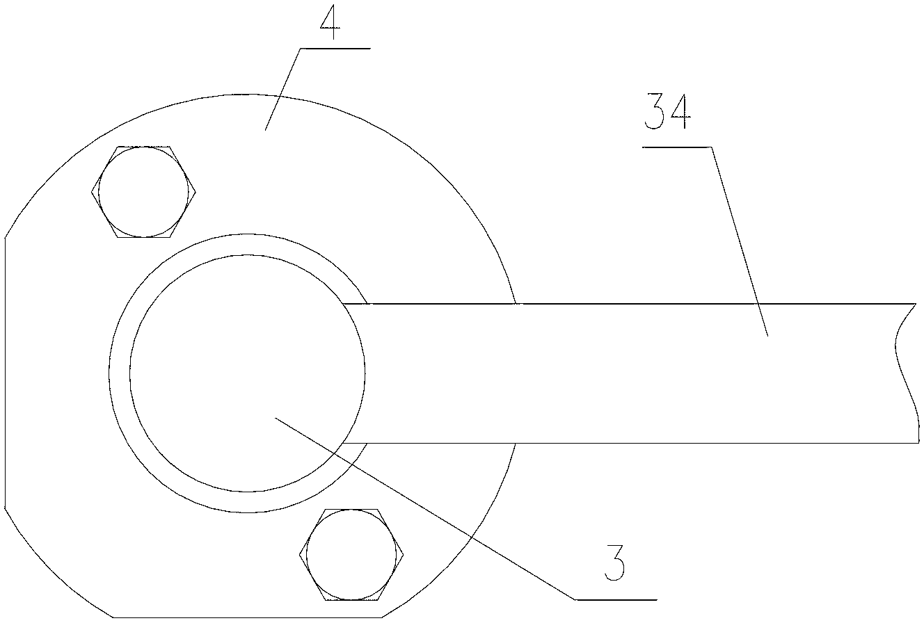
[0019] Please also refer to Figure 1 to Figure 4 , a loading valve for a hydraulic component test bench provided by the present invention, comprising a valve body 1, the bottom end of the valve body 1 is a plane and a bottom plate 2 is provided under the bottom end of the plane, and the valve body 1 is fixed with the bottom plate 2 by screws . The valve body 1 is provided with a stepped first annular cavity 11 with an open right end in the length direction, and an oil inlet 12 and an oil outlet 13 that communicate with the first annular cavity 11 and are vertically forward are arranged side by side on the valve b...


PUM


Abstract

The invention discloses a loading valve for a hydraulic part test bench. The loading valve for the hydraulic part test bench comprises a valve body, wherein a first stepped annular cavity with the right end opening is arranged along the length direction of the valve body, an oil inlet and an oil outlet which are communicated with the first annular cavity and vertically forward are arranged on the valve body in paralleling mode, a rotatable valve core is arranged in the first annular cavity of the valve body in sealing mode, the right end of the valve core stretches out of the valve body, a second annular cavity with the left end opening is arranged along the length direction of the valve core, an oil outlet adjusting channel which is communicated with the second annular cavity and vertically forward is arranged on the valve core, the oil outlet adjusting channel on the valve core is communicated with the oil outlet on the valve body when the loading valve is static, the oil outlet adjusting channel comprises a circular channel, a triangular pyramid groove with the vertex upwards is arranged on a connecting portion of the top of the circular channel and the outside surface of the valve core, and the lower end of the triangular pyramid groove leads to the circular channel. Compared with the prior art, the loading valve for the hydraulic part test bench has the advantages of being simple and compact in structure, small in size, low in cost, convenient to operate, and high in accuracy and good in stability.

Description

technical field [0001] The invention relates to a hydraulic component loading device, in particular to a loading valve for a hydraulic component test bench. Background technique [0002] With the continuous development of science and technology and industry, various performance requirements for hydraulic parts are gradually increasing. The hydraulic part test bench is a simulation device for the loading force in the actual working conditions of the hydraulic parts. The force has the characteristics of large fluctuations over time and many uncertain factors, so that the force loading accuracy, stability, response speed and sensitivity of the loading device for the hydraulic parts test bench directly affect the test accuracy of the hydraulic parts test bench. It is particularly important for the test results to accurately reflect various performance indicators of hydraulic components working under field conditions. In the prior art, the hydraulic loading devices used in the h...

Claims


Application Information

Patent Timeline
Patent Type & Authority Applications(China)
IPC IPC(8): F16K5/12
Inventor 梁俊徐诚葛先阳
Owner HEFEI AUTOMOBILE OIL PUMP
Why Eureka
Try Eureka