
Installment structure of GRG decorative panel

A technology of installation structure and decorative panel, applied in the field of installation structure of GRG decorative panel, can solve the problems of lack of installation method of GRG decorative panel, restricting the promotion and application of GRG decorative panel, etc., so as to save workload, low installation cost and high installation efficiency Effect

Active Publication Date: 2013-09-04
SHENZHEN HONGTAO DECORATION
View PDF3 Cites 14 Cited by
  • Summary
  • Abstract
  • Description
  • Claims
  • Application Information

AI Technical Summary

Problems solved by technology

The existing technology lacks a simple, practical and convenient installation method developed for laying GRG decorative panels on a large area on a plane, which restricts the promotion and application of GRG decorative panels in the architectural decoration industry

Method used


Image

  • Installment structure of GRG decorative panel
  • Installment structure of GRG decorative panel
  • Installment structure of GRG decorative panel

Examples


Embodiment 1

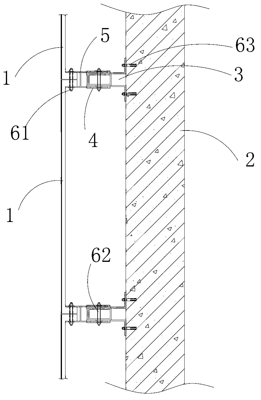
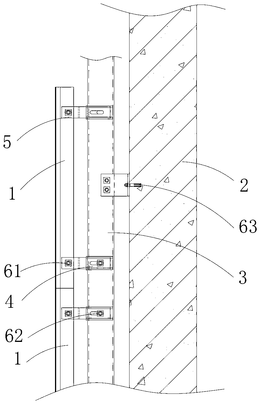
[0034] Such as figure 2 , 3 In the installation structure of the GRG veneer, the front side of the veneer 1 made of GRG material is a wood veneer, and the second mounting part 5 and the first mounting part 4 are fixed on the vertical keel 3, and the vertical keel 3 is fixed 2 surfaces on building walls. Each connecting piece adopts bolts. The second mounting part 5 and the first mounting part 4 are made of aluminum alloy or stainless steel.

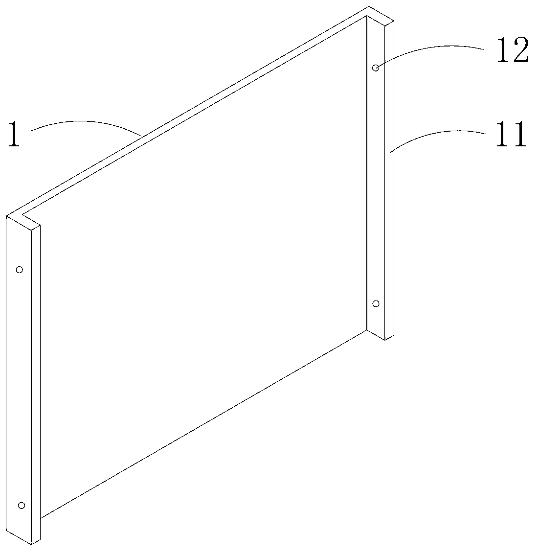
[0035] The veneer 1 is regularly arranged on the surface of the wall 2, such as figure 1 As shown, the structure is provided with vertical installation strips 11, and the vertical installation strips 11 are located on the left and right sides of the back of the GRG veneer 1. During production and processing, the sides of the GRG veneer are directly thickened and formed. A fourth fixing hole 12 through left and right is respectively opened on the upper part and the lower part of the vertical mounting bar 11 on each side.

[0036] The...

Embodiment 2

[0042] Such as Figure 9 , 10 The installation structure of the GRG veneer shown is different from that of Embodiment 1 in the following description.

[0043] Such as Figure 8 As shown, there is no fourth fixing hole 12 at the upper and lower ends of the vertical mounting strip 11 on the back of the GRG veneer 1, but an upper card slot 13 is provided on its upper side, and a lower card slot 14 is provided on the lower side.

[0044] Such as Figure 11 , 12 , 13, the left end of the second mounting part 5 is not provided with a third U-shaped opening 51, but is provided with an upper clamping plate 55 and a lower clamping plate 56; The lower clamping slot 14 of the upper decorative panel in the panel 1 and the lower clamping plate 56 are inserted into the upper clamping slot 13 of the lower decorative panel, thereby connecting and fixing the left end of the second mounting part 5 with two adjacent vertical mounting bars 11 . For the upper card slot of the highest GRG panel ...


PUM


Abstract

The invention discloses an installment structure of a GRG decorative panel. The installment structure of the GRG decorative panel comprises the GRG decorative panel 1 fixed on a building wall body 2. The left side and the right side of the back of the GRG decorative panel 1 are respectively thickened, and therefore vertical installment strips 11 are formed on the left side and the right side respectively. A vertical keel 3 is fixed on the wall body 2. The wall body 2 is further provided with a first installment piece 4 and a second installment piece 5, wherein the first installment piece 4 is fixed on the vertical keel 3, the left end of the second installment piece 5 is fixed with vertical installment strips 11, and the right end of the second installment piece 5 is fixed with the first installment piece. Because the GRG panel is provided with the vertical installment strips, the vertical keel is arranged on the wall body, transverse keels are not needed, the first installment piece is connected with the second installment piece to replace the function of the transverse keels, installment work load is small, installment cost is low, and installment efficiency is high.

Description

technical field [0001] The invention relates to an installation structure of a GRG veneer. Background technique [0002] GRG (Glass-fiber Reinforced Gypsum, glass fiber reinforced gypsum) is a special modified fiber gypsum decorative material. The randomness of the shape makes it the first choice for architects who require individuality. Its unique material composition is strong enough to resist the external environment. damage, deformation and cracking. Its shape selection is rich and arbitrary, and GRG products that can adopt pre-casting processing technology can customize any artistic shape such as single curved surface, hyperboloid surface, three-dimensional cladding, hollow pattern, relief pattern, etc., to give full play to the design. It also has the advantages of high strength, light weight, no deformation, no cracking, and good sound wave reflection performance. [0003] But also because GRG material has the characteristics of high strength, unlike the installatio...

Claims


Application Information

Patent Timeline
Patent Type & Authority Applications(China)
IPC IPC(8): E04F13/23
Inventor 李喆平肖发明刘晓聪刘年新
Owner SHENZHEN HONGTAO DECORATION
Learn More