
Building roof and photovoltaic component

A technology of photovoltaic modules and raised parts, applied in the field of solar energy, can solve the problems of inconvenient maintenance, inspection and maintenance, repeated construction, damage to the overall structure of the roof and load-bearing design, etc.

Active Publication Date: 2010-11-10
YINGLI ENERGY CHINA
View PDF4 Cites 8 Cited by
  • Summary
  • Abstract
  • Description
  • Claims
  • Application Information

AI Technical Summary

Problems solved by technology

[0004] 1) It cannot be designed as an integrated structure with the roof, and a layer of photovoltaic modules is laid on the existing roof. The construction time is long and there is a problem of repeated construction;
[0005] 2) Existing flat roofs have a single variety and poor aesthetics of the roof;
[0006] 3) The roof formed by flat-plate photovoltaic modules has poor deformation resistance, resulting in a shorter service life of the roof;
[0007] 4) In addition, the flat-panel photovoltaic module is easy to reflect light, and it will cause serious light pollution to the space after being laid in a large area;
[0008] 5) It needs to be equipped with professional installation equipment, equipment and personnel during its installation, which is time-consuming and labor-intensive
[0009] 6) Moreover, it is inconvenient to repair, inspect and maintain after installation, and it is necessary to reserve a certain space on the roof for secondary installation of power lead wires;
[0010] 7) When the existing photovoltaic modules are installed, it is necessary to add fixing devices to the roof later, which will destroy the original overall structure and load-bearing design of the roof, and cause damage to the roof of the house

Method used


Image

  • Building roof and photovoltaic component
  • Building roof and photovoltaic component
  • Building roof and photovoltaic component

Examples


Embodiment Construction

[0031] The core of the present invention is to provide a photovoltaic module, which can effectively reduce the installation difficulty of the photovoltaic module and improve the installation efficiency of the photovoltaic module. Another core of the present invention is to provide a building roof formed by the above-mentioned photovoltaic modules.

[0032] The upper and lower orientation words involved in this article are defined based on the position of the photovoltaic module when it is working normally. It should be understood that the orientation words used herein shall not limit the protection scope of this patent.

[0033] In order to enable those skilled in the art to better understand the solution of the present invention, the present invention will be further described in detail below in conjunction with the accompanying drawings and specific embodiments.

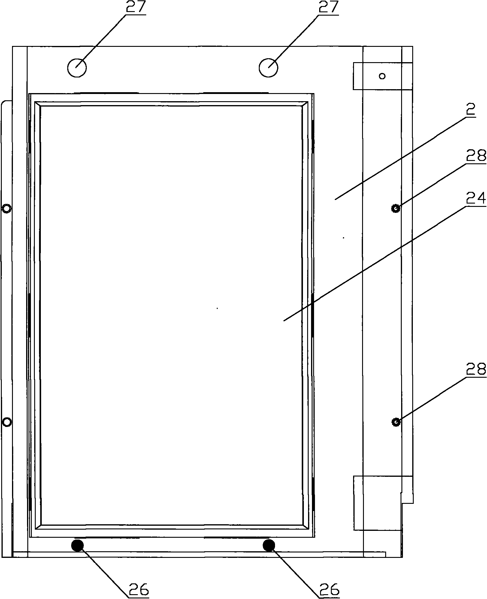
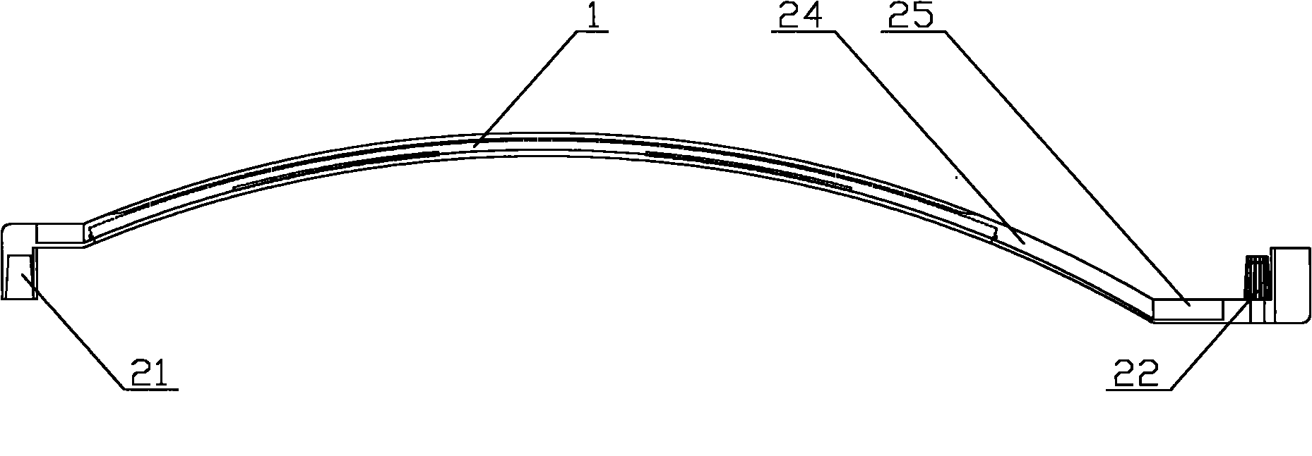
[0034] Please refer to Figure 1 to Figure 4 , figure 1 It is a top view of a specific embodiment of the phot...


PUM


Abstract

The invention discloses a photovoltaic component which can be matched with other photovoltaic components for use and comprises a solar cell (1) and an outer frame (2) protecting the solar cell (1), wherein the outer frame (2) comprises a depressed part (21) and a raised part (22) which is opposite to the depressed part (21); furthermore, in the adjacent two photovoltaic components, the depressed part (21) of one is matched and connected with the raised part (22) of the other one. The photovoltaic component can replace a traditional roof tile to be mounted on a roof and become a whole with the roof, thereby being unnecessary to increase a mounting member of the photovoltaic component, and the structural designs of load-bearing, waterproofing and the like damaging the roof in the later stage, being convenient to mount, being capable of being mounted by staff with the mounting skill of the traditional roof tile, having no need of professional mounting device, staff and the like, improving the mounting efficiency of the photovoltaic component and reducing the mounting cost of a building roof formed by the photovoltaic component. The invention further provides the building roof comprising the photovoltaic component.

Description

technical field [0001] The present invention relates to the field of solar energy, in particular to a photovoltaic assembly, and also to a building roof formed by the above photovoltaic assembly. Background technique [0002] Solar energy is a low-carbon renewable energy source. Compared with conventional energy sources, it is easy to use and low in cost. Solar photovoltaic modules are used to directly convert sunlight energy into electrical energy, supply electrical equipment or transmit electrical energy to the grid, and are suitable for current energy conservation. The social development needs of consumption reduction. Photovoltaic modules can be installed in various places, and the top floor of the house has a wide space for use. Installing photovoltaic modules on the roof is a matter of benefit to the country and the people. [0003] Existing photovoltaic modules are designed with a flat structure when installed on the roof, and can only be installed as a flat roof. Su...

Claims


Application Information

Patent Timeline
IPC IPC(8): H01L31/042E04D13/18H02S20/23
CPCY02E10/50Y02B10/12Y02B10/10
Inventor 王士元
Owner YINGLI ENERGY CHINA
Learn More