
Radiotherapy equipment and radiotherapy system with radiotherapy equipment

A radiotherapy and equipment technology, applied in the field of medical equipment, can solve problems such as poor treatment effect, low treatment efficiency, and increased patient burden, and achieve the effects of improving dose distribution capabilities, improving treatment efficiency, and ensuring treatment accuracy

Inactive Publication Date: 2013-09-04
TSINGHUA UNIV
View PDF3 Cites 17 Cited by
  • Summary
  • Abstract
  • Description
  • Claims
  • Application Information

AI Technical Summary

Problems solved by technology

[0004] However, in the current tumor helical tomotherapy system, when the slice thickness is set too large (such as ≥ 5mm), the conformity of the tumor target area is significantly reduced, the dose distribution cannot meet the clinical needs, and the treatment effect is not good. When the slice thickness is set too small (such as ≤1mm), the treatment efficiency is low, and the working time of the magnetron increases under the same conditions, which reduces its service life and indirectly increases the burden on patients
The reason for the above problems is: the binary multi-leaf collimator used in the traditional helical tomographic intensity-modulated radiotherapy, the blades are driven by compressed air, and work in two states of switch, which cannot realize accurate positioning at the middle position of the blade travel, and cannot realize Adjustment and precise control of the speed, so that the beam intensity modulation in the direction of the fault thickness cannot be achieved

Method used


Image

  • Radiotherapy equipment and radiotherapy system with radiotherapy equipment
  • Radiotherapy equipment and radiotherapy system with radiotherapy equipment
  • Radiotherapy equipment and radiotherapy system with radiotherapy equipment

Examples


Embodiment Construction

[0028] Embodiments of the present invention are described in detail below, examples of which are shown in the drawings, wherein the same or similar reference numerals designate the same or similar elements or elements having the same or similar functions throughout. The embodiments described below by referring to the figures are exemplary and are intended to explain the present invention and should not be construed as limiting the present invention.

[0029] In describing the present invention, it should be understood that the terms "center", "longitudinal", "transverse", "length", "width", "thickness", "upper", "lower", "front", " Orientation or position indicated by "back", "left", "right", "vertical", "horizontal", "top", "bottom", "inner", "outer", "clockwise", "counterclockwise", etc. The relationship is based on the orientation or positional relationship shown in the drawings, and is only for the convenience of describing the present invention and simplifying the descrip...


PUM


Abstract

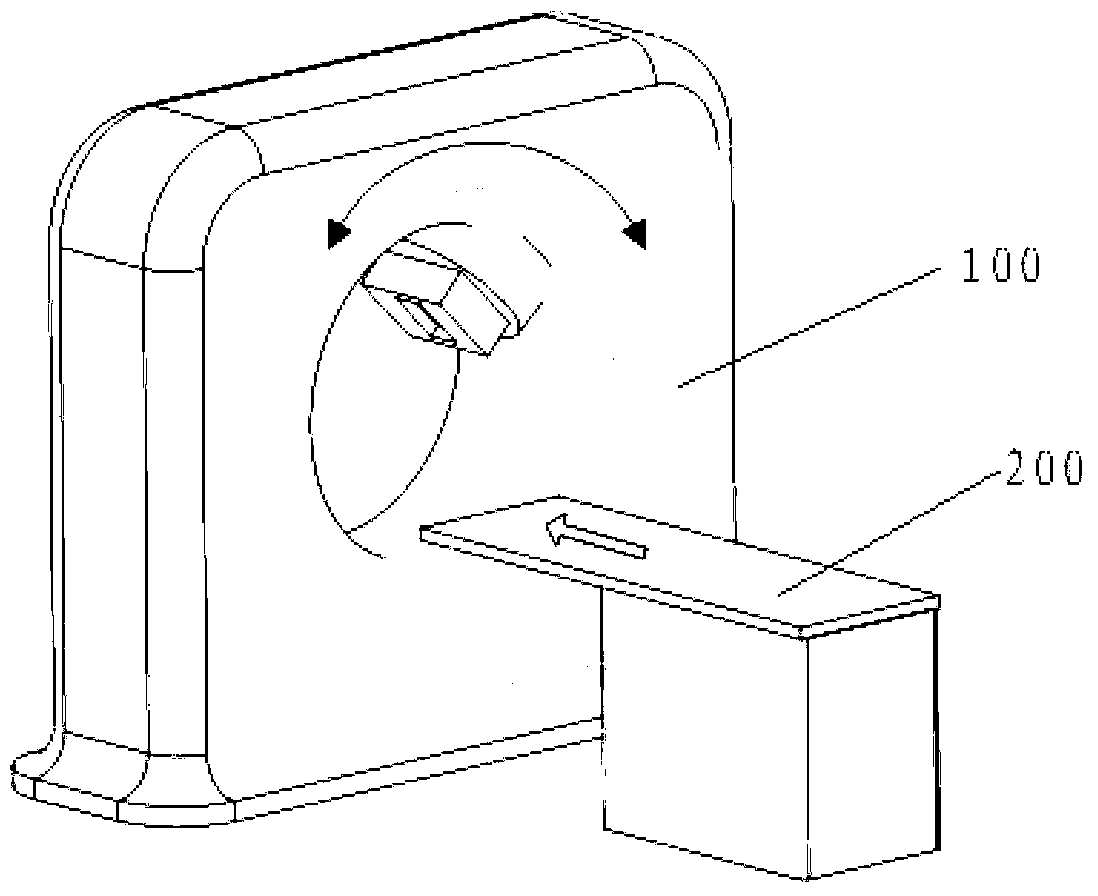
The invention discloses radiotherapy equipment and a radiotherapy system with the radiotherapy equipment. The radiotherapy equipment comprises a fixed cabinet, a rotary support, a main collimator, a radiation source and a multi-leaf collimator, wherein the rotary support is rotationally arranged on the fixed cabinet, and is provided with the radiation source, the main collimator is arranged on the radiation source, the multi-leaf collimator is mounted on the fixed cabinet and comprises multiple parallel leaf groups, each leaf group comprises a first leaf, a second leaf, a first linear motor and a second linear motor, the first and second leaves are oppositely arranged, the first linear motor is connected with the first leaf to drive the first leaf to move, and the second linear motor is connected with the second leaf to drive the second leaf to move. The radiotherapy equipment adopts the linear motors to drive the leaves to move, thus realizing the accurate control on the speed and position of the leaves and further improving the curing precision and efficiency.

Description

technical field [0001] The invention relates to the field of medical equipment, in particular to a radiation therapy device and a radiation therapy system with the radiation therapy device. Background technique [0002] The main principle of Intensity Modulated Radiotherapy (IMRT) can be summarized as follows: the intensity of the incident beam is modulated by an intensity-modulated device such as a collimator to achieve dose accumulation of X-rays. Its fundamental purpose is to improve the spatial conformity between the beam and the tumor target area, while avoiding key tissues and organs and reducing the dose of adjacent normal tissues. In intensity-modulated radiation therapy, the key executive component is the multi-leaf collimator (Multi-leaf Collimator, MLC, also known as multi-leaf grating, multi-leaf aperture), and the multi-leaf collimator is composed of one or more groups of leaves. The combination of mechanical movement changes of the blades changes the beam shap...

Claims


Application Information

Patent Timeline
IPC IPC(8): A61N5/10
Inventor 叶佩青周东张震
Owner TSINGHUA UNIV
Learn More