Multi-segment-type cascading driving circuit

A driving circuit, multi-stage technology, applied in the direction of lamp circuit layout, electric light source, lighting device, etc., can solve the problems of increased development time, different driving conditions, complex circuits, etc., to improve efficiency, power factor, and turn-on time The effect of refinement and simple circuit connection

Active Publication Date: 2013-08-28
SHANGHAI YAMING LIGHTING
View PDF3 Cites 6 Cited by
  • Summary
  • Abstract
  • Description
  • Claims
  • Application Information

AI Technical Summary

Problems solved by technology

However, when driving a cascade combination of multiple LEDs in series and parallel, due to the different driving conditions, it brings inconvenience to the operation, control and maintenance of the LED lamp group
[0003] At present, LED drive circuits are of different quality, some are very simple in order to reduce the cost, the power factor is only about 0.5, and the luminous efficiency is very low, which cannot meet the market demand for high-efficiency and energy-saving products, and some are in pursuit of high-performance requirements. , the circuit is very complex, using a large number of restrictive devices such as electrolytic capacitors and inductors, the cost is greatly increased, the circuits of different products are not the same, the development of the circuit is also relatively difficult, and the development time is increased. Due to the complexity of the circuit, the volume of the product Relatively large, affecting the overall design of lighting products

Method used


Image

  • Multi-segment-type cascading driving circuit
  • Multi-segment-type cascading driving circuit
  • Multi-segment-type cascading driving circuit

Examples


Embodiment Construction

[0033] The implementation of the present invention will be illustrated by specific specific examples below, and those skilled in the art can easily understand other advantages and effects of the present invention from the contents disclosed in this specification.

[0034] It should be noted that the structures, proportions, sizes, etc. shown in the drawings attached to this specification are only used to match the content disclosed in the specification, for those who are familiar with this technology to understand and read, and are not used to limit the implementation of the present invention. Limiting conditions, so there is no technical substantive meaning, any modification of structure, change of proportional relationship or adjustment of size, without affecting the effect and purpose of the present invention, should still fall within the scope of the present invention. The disclosed technical content must be within the scope covered. At the same time, terms such as "upper"...


PUM


Abstract

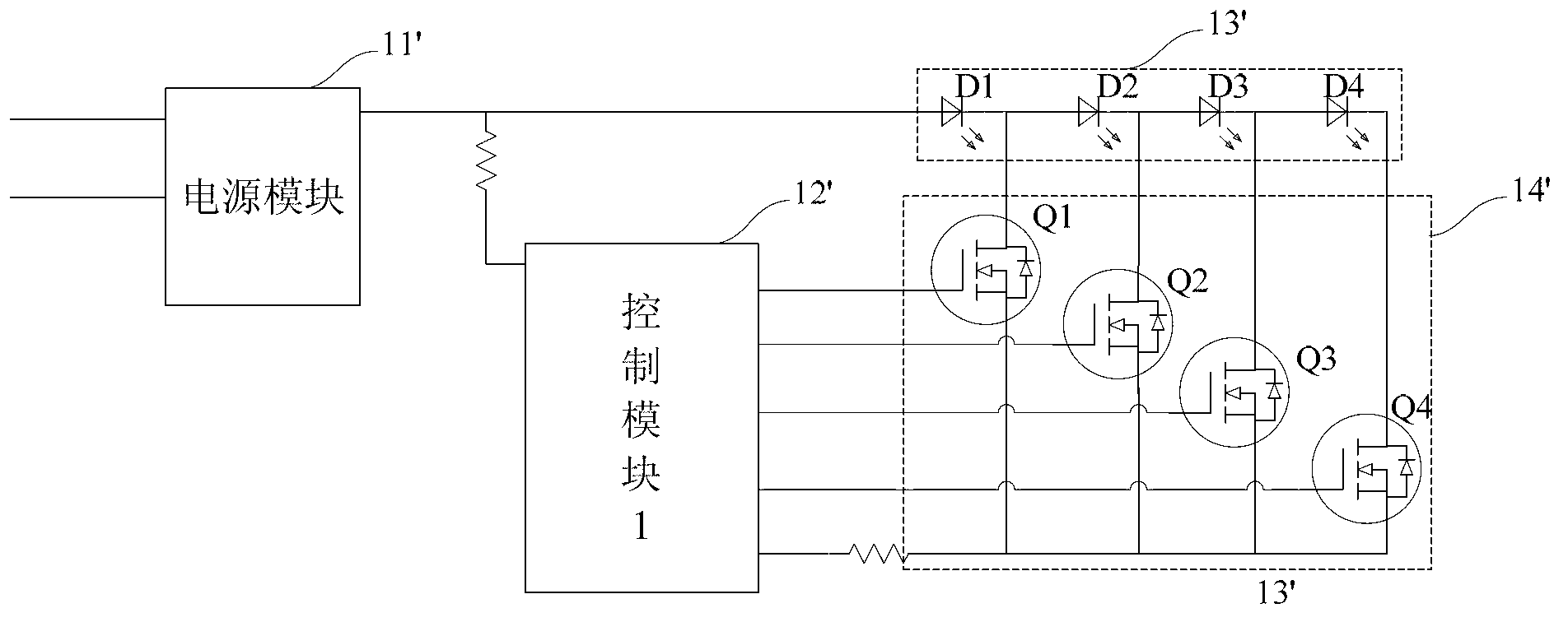
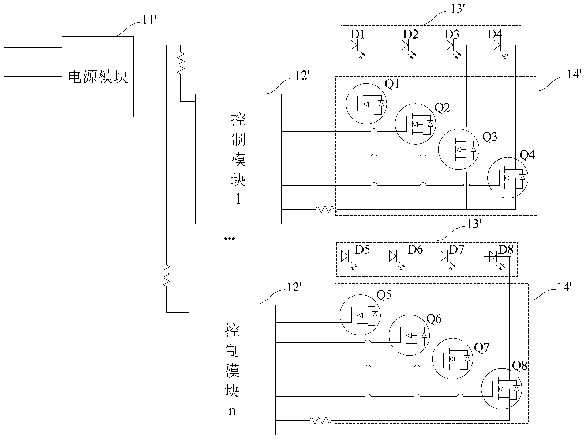
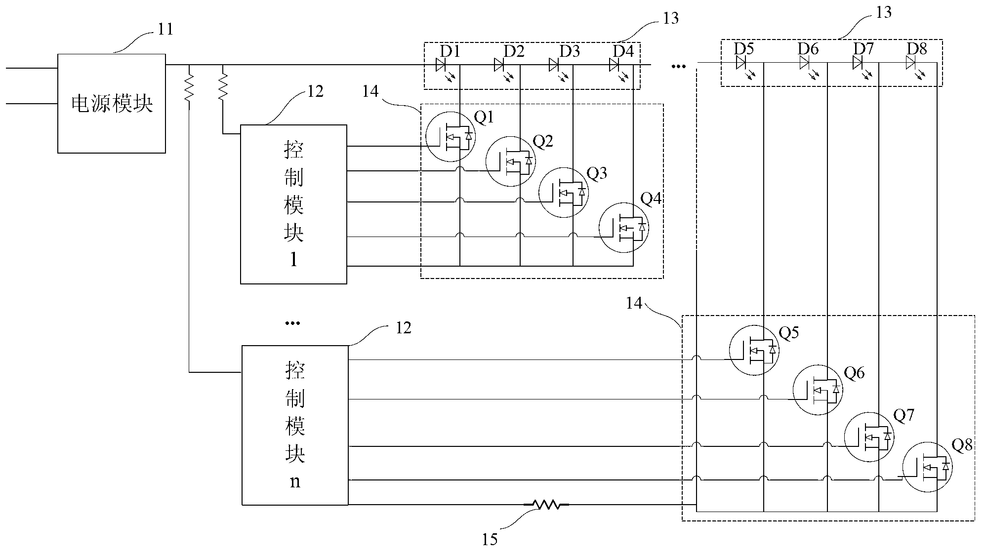
The invention provides a multi-segment-type cascading driving circuit which comprises a power module, a plurality of control modules sequentially connected onto an output line of the power module, a plurality of load modules sequentially connected in series on the output line of the power module and correspondingly connected with the plurality of control modules as well as controlled by the corresponding control modules to run, and a plurality of switching modules connected between the corresponding control modules and the load modules and used for controlling the load modules to run through commands of the control modules, wherein the output terminal of the control module which is lastly connected to the output line of the power module is connected with a stable resistor; each switching module is formed by MOS (Metal Oxide Semiconductor) field effect transistors; each load module is formed by light emitting diodes; a current-limiting resistor is connected between the power module and each MOS field effect transistor; and the sequence of the plurality of control modules connected to the output line is opposite to the sequence of the plurality of correspondingly-controlled load modules on the output line. As the multi-segment-type cascading driving circuit is used, the efficiency and the power factor of a power supply are improved.

Description

technical field [0001] The invention relates to the technical field of LED drive circuits, in particular to a multi-stage cascaded drive circuit. Background technique [0002] Light Emitting Diode (LED for short) is an optoelectronic semiconductor element that emits light by exciting electrons with an external voltage. It has the advantages of low power consumption, high brightness, long life, and small size. At present, a typical high luminous flux LED device can produce a luminous flux of several lumens to tens of lumens. The updated design can be a cascade combination of multiple LEDs in series, that is, multiple devices can be installed in a single assembly, or more LEDs can be integrated in one device, so that the output lumens are equivalent to small incandescent lamps . For example, a high-power 12-chip monochrome LED device can output 200 lumens of light energy and consume between 10 and 15 watts. LEDs have been widely used in a variety of lighting equipment, such...

Claims


Application Information

Patent Timeline
IPC IPC(8): H05B37/02
Inventor 李宝泉徐小良肖祥陈佐兴
Owner SHANGHAI YAMING LIGHTING
Why Eureka
Try Eureka