
Reactive compensation configuration method based on static and transient voltage stability constraint

A technology of transient voltage stabilization and static voltage stabilization, applied in reactive power compensation, reactive power adjustment/elimination/compensation, etc., can solve problems of convergence speed due to insufficient memory, complex control states of units and systems, and difficulty in finding the global optimum To solve problems such as improving the ability to resist the risk of voltage instability, improving the level of safe, stable, efficient and economical operation, and improving accuracy and effectiveness

Active Publication Date: 2013-08-28
CHINA ELECTRIC POWER RES INST +1
View PDF2 Cites 13 Cited by
  • Summary
  • Abstract
  • Description
  • Claims
  • Application Information

AI Technical Summary

Problems solved by technology

However, with the continuous expansion of the scale of the interconnected power system and the continuous improvement of the voltage level, especially after the UHV large power grid is put into operation, the power grid covers a vast area and has a large number of nodes. Both the traditional reactive power optimization algorithm and the artificial intelligence algorithm have insufficient memory and convergence. Dimensional disaster problems such as speed, and it is difficult to find the global optimal solution
There are still some problems in the practical application of such algorithms
[0006] In addition, with the continuous expansion of grid scale and transmission capacity, as well as the extensive adoption of new transmission technologies, such as the adoption of large-scale power electronic devices and the development of flexible AC transmission technology (FACTS), the control status of units and systems has become increasingly complex. Many new stability issues follow

Method used


Image

  • Reactive compensation configuration method based on static and transient voltage stability constraint
  • Reactive compensation configuration method based on static and transient voltage stability constraint
  • Reactive compensation configuration method based on static and transient voltage stability constraint

Examples


Embodiment Construction

[0029] The present invention will be described in further detail below in conjunction with the accompanying drawings.

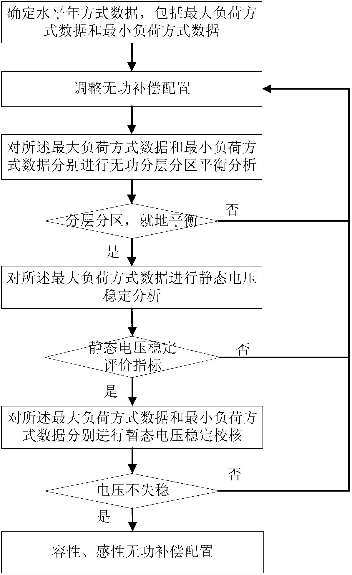
[0030] figure 1 It is a flowchart of the reactive power compensation configuration method based on static and transient voltage stability constraints.

[0031] Taking the research on the configuration of reactive power compensation at a certain level in Guizhou power grid as an example, there are the following examples:

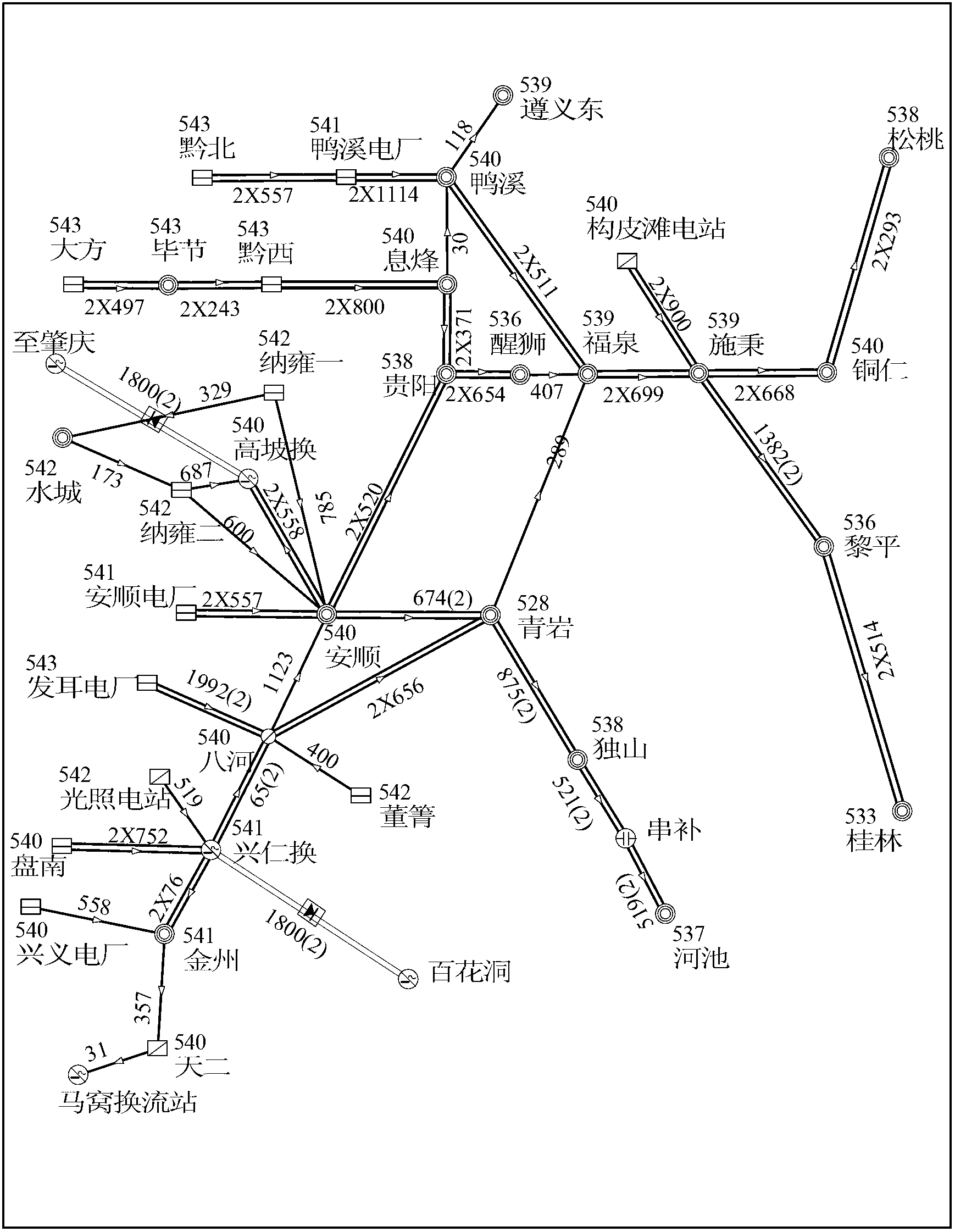
[0032] (1) Build the horizontal annual mode data of Guizhou power grid, including the maximum load mode data and the minimum load mode data; the maximum load mode power flow diagram is as follows figure 2 shown;

[0033] (2) According to the constraint conditions of reactive power hierarchical partition balance analysis (reactive power hierarchical partition balance analysis constraints include that the power factor of the main transformer of 220kV and above shall not be less than 0.95 under the maximum load condition, and bet on the mini...


PUM


Abstract

The invention provides a reactive compensation configuration method based on a static and transient voltage stability constraint. The method comprises the following steps: determining level year data; performing reactive delaminating and districting balance analysis; performing static voltage stability analysis; performing transient voltage stability check; and determining reactive compensation configuration. According to the method, reasonable final reactive compensation configuration is provided through comprehensive optimization of the reactive delaminating and districting balance analysis, static voltage stability analysis and transient voltage stability check. Due to the adoption of the method, the accuracy and effectiveness of reactive compensation configuration can be effectively increased, unnecessary investment is avoided, and waste is reduced; and meanwhile, the voltage instability risk resistance of a power grid is improved greatly, and safe, stable, efficient and economic running level of the power grid is raised.

Description

technical field [0001] The invention belongs to the technical field of power systems, and in particular relates to a reactive power compensation configuration method based on static and transient voltage stability constraints. Background technique [0002] On the basis of ensuring the safe and stable operation of the power grid, in order to improve the economic benefits of power grid operation, reduce active power loss and investment, and improve power quality, it is necessary to rationally configure reactive power compensation devices and reasonably control their switching, and strive to achieve "reactive power distribution". layer partition balance" goal. Insufficient or unbalanced reactive power, on the one hand, causes the system voltage to drop, threatens the stability of the power grid, and may induce serious faults such as voltage collapse; on the other hand, it may endanger the safety of the equipment itself and cause unnecessary waste of investment. [0003] At pre...

Claims


Application Information

Patent Timeline
IPC IPC(8): H02J3/18
CPCY02E40/30
Inventor 唐晓骏刘国权罗红梅谢良陈湘钟以林申旭辉罗竹平尚慧玉何向刚李晓珺王力立李媛媛马冲吉平李雪凌周俊陈青林俊杰
Owner CHINA ELECTRIC POWER RES INST
Learn More