
Mounting clamp of ultrasonic sensor

A technology for installing fixtures and sensors, used in instruments, measuring devices, manufacturing tools, etc., can solve the problems of ultrasonic flowmeter errors, sensors are not in a plane, and cannot be measured, and achieve reliable clamping results.

Active Publication Date: 2013-08-28
PETROCHINA CO LTD
View PDF4 Cites 17 Cited by
  • Summary
  • Abstract
  • Description
  • Claims
  • Application Information

AI Technical Summary

Problems solved by technology

[0002] Online calibration with an ultrasonic flowmeter, when installing an ultrasonic sensor, it often happens that the installed sensor is not in the same plane, or the plane where it is located cannot be guaranteed to be parallel to the axis of the straight pipe section, or it is impossible to measure whether it is in a reasonable clamping position, especially in monophonic testing During the process, the distance between the sensors is inaccurate, and the distance between the two sensors on the opposite side cannot be measured or adjusted accurately, which will affect the signal of the online calibration of the ultrasonic flowmeter, and human factors cause large errors in the online calibration of the ultrasonic flowmeter.

Method used


Image

  • Mounting clamp of ultrasonic sensor
  • Mounting clamp of ultrasonic sensor
  • Mounting clamp of ultrasonic sensor

Examples


Embodiment Construction

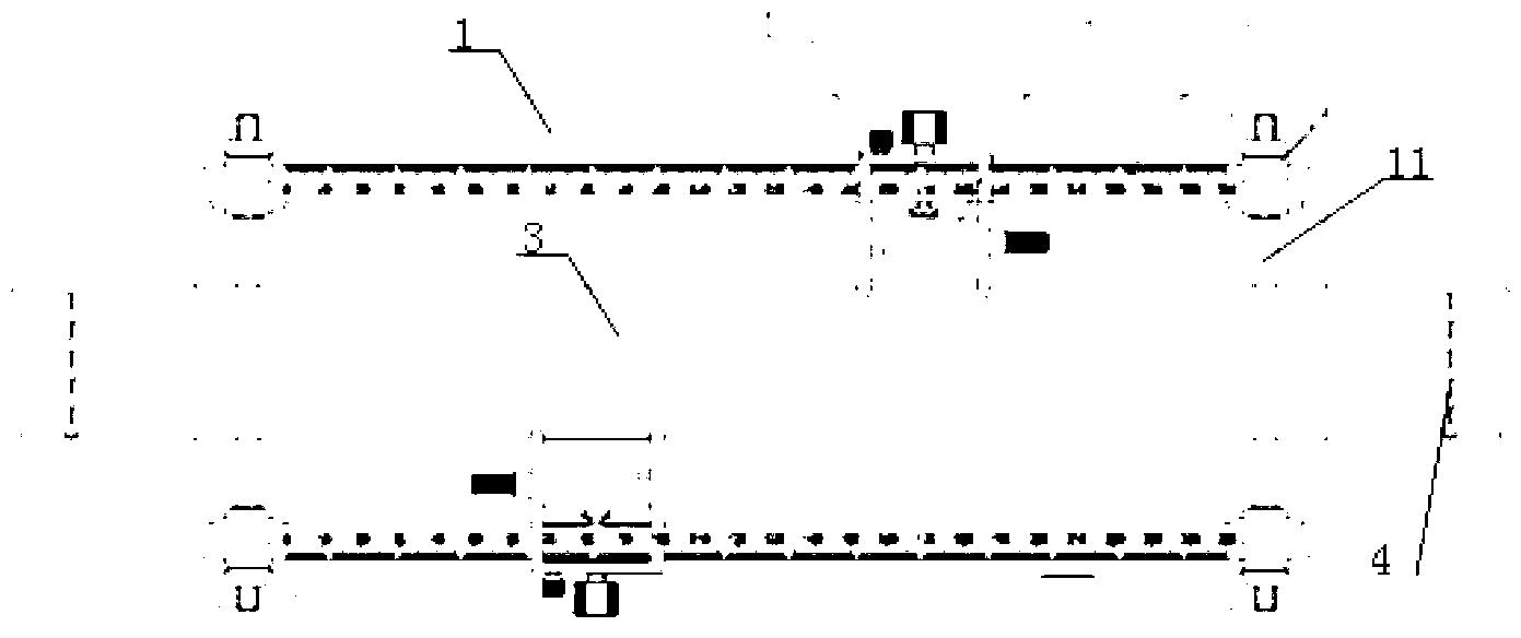
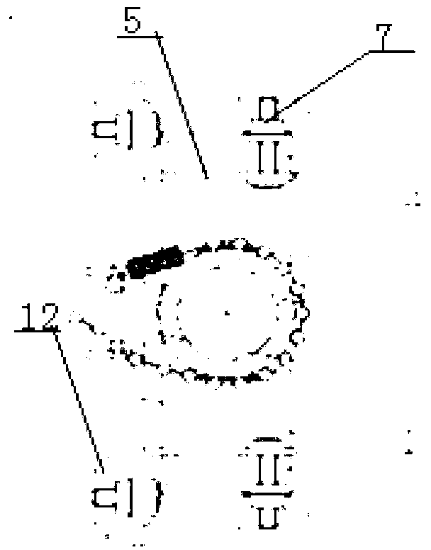
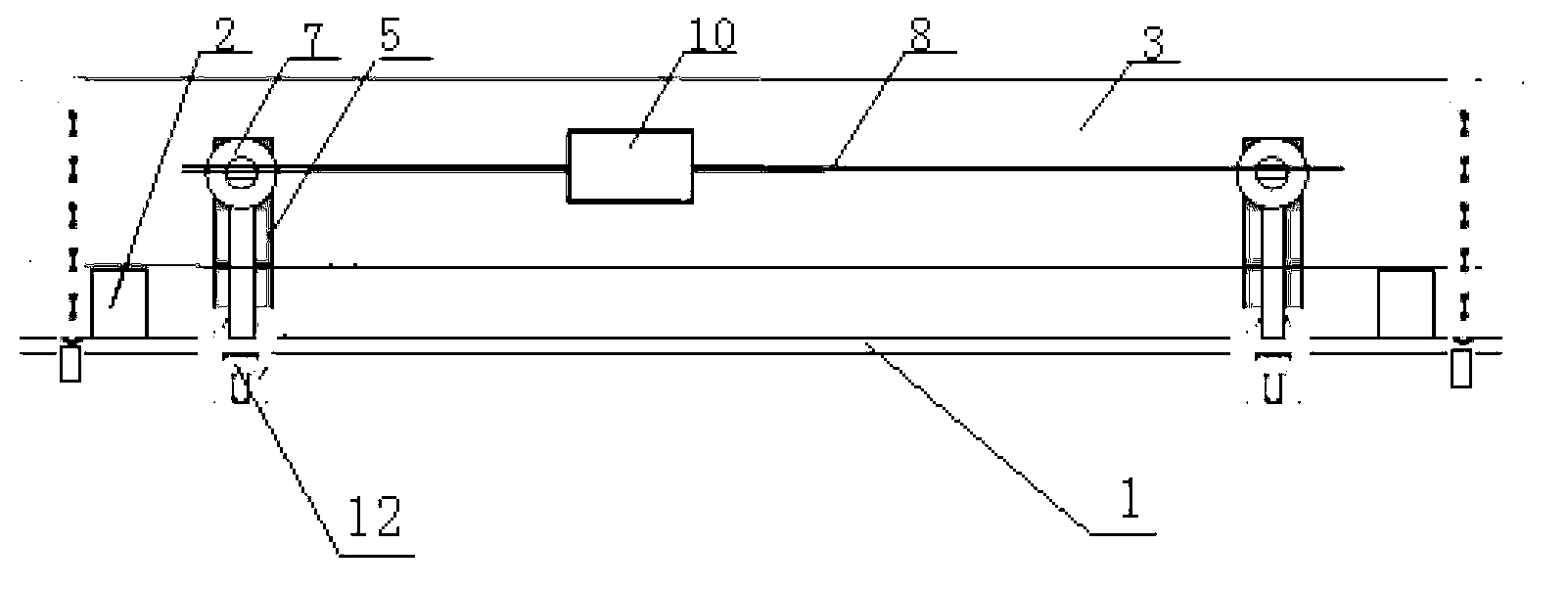
[0011] see figure 1 , figure 2 , image 3 and Figure 4 , An ultrasonic sensor installation jig provided by an embodiment of the present invention includes a mounting plate 1 , a positioning block 2 , a bracket rail 5 , a buckle 7 , a scale slider 8 , and a sensor bracket 10 . The positioning block 2 is fixed on the center line at both ends of the mounting plate 1, and the straight pipe section 3 is positioned by the positioning block 2, which ensures that the datum of the mounting plate 1 is parallel to the straight pipe section 3; the mounting plate 1 is provided with four symmetrical mounting plate tracks 11 , each mounting plate track 11 is connected to the support track 5 through the mounting plate track buckle 12, and the buckle 7 is connected to the chute of the support track 5. By adjusting the distance between the support track 5, the sensor 9 can be used in different pipe diameters. Clamping on the straight pipe section 3, and by adjusting the height of the buckl...


PUM


Abstract

The invention provides a mounting clamp of an ultrasonic sensor. The mounting clamp comprises a mounting plate, positioning blocks which are arranged at the central line positions of the two ends of the mounting plate, bracket rails which are respectively arranged on four symmetrical mounting plate rails of the mounting plate, buckles which are respectively arranged on slide ways of the bracket rails and can adjust the height, a scale slide strip with two ends which are respectively fixed on the buckles, and a sensor bracket which is arranged on the scale slide strip and is used for mounting the ultrasonic sensor. The mounting clamp of the ultrasonic sensor disclosed by the invention is simple in structure and convenient to use; an ultrasonic sensor probe can be effectively mounted according to straight pipe sections with different apertures and accurate positions of clamping the ultrasonic sensor probe on the straight pipe sections can be guaranteed; and a mounting distance between the sensors can be visually read and the mounting distance between the sensors can also be adjusted according to requirements.

Description

technical field [0001] The invention relates to an installation fixture, in particular to an ultrasonic sensor installation fixture. Background technique [0002] Online calibration with an ultrasonic flowmeter, when installing an ultrasonic sensor, it often happens that the installed sensor is not in the same plane, or the plane where it is located cannot be guaranteed to be parallel to the axis of the straight pipe section, or it is impossible to measure whether it is in a reasonable clamping position, especially in monophonic testing During the process, the distance between the sensors is inaccurate, and the distance between the two sensors on the opposite side cannot be measured or adjusted accurately. This will affect the signal of the online calibration of the ultrasonic flowmeter. Human factors cause large errors in the online calibration of the ultrasonic flowmeter. Contents of the invention [0003] The technical problem to be solved by the present invention is to...

Claims


Application Information

Patent Timeline
IPC IPC(8): G01F25/00B25B11/00
Inventor 常彦荣邵东波薛建强姚斌王守虎张随望陈阵郑刚高超君李建中陆小兵王俊涛王勇王薇何汝贤隋蕾王晓娥涂学万
Owner PETROCHINA CO LTD
Learn More