A triggering system of thyristor switched capacitor valve set

A thyristor switching, thyristor valve technology, applied in flexible AC transmission systems, reactive power adjustment/elimination/compensation, etc. problem, to achieve the effect of easy circuit startup, easy integration, and simple realization

Active Publication Date: 2013-08-21
NR ELECTRIC CO LTD +1
View PDF6 Cites 6 Cited by
  • Summary
  • Abstract
  • Description
  • Claims
  • Application Information

AI Technical Summary

Problems solved by technology

On the one hand, its high-potential energy harvesting circuit is a voltage energy harvesting method, and after the thyristor switching capacitor valve group is turned on, there is no voltage at both ends of the valve group, and the energy required for triggering cannot be obtained; on the other hand, its BOD protection threshold voltage is set close to the thyristor withstand voltage. However, in the application of thyristor switching capacitor valve group, if the thyristor valve group is triggered and opened at this moment, a huge voltage and current impact will inevitably occur in the system, and the equipment will be damaged in severe cases.
Another example is the Chinese invention patent with application number 200810100878.7, which discloses a thyristor valve high-potential electronic board, which can trigger two common-cathode thyristors at the same time with one trigger command, but each energy harvesting circuit needs an Energy-taking current transformers, and need to be equipped with complex power conversion circuit

Method used


Image

  • A triggering system of thyristor switched capacitor valve set
  • A triggering system of thyristor switched capacitor valve set
  • A triggering system of thyristor switched capacitor valve set

Examples


Embodiment Construction

[0036] The technical solutions of the present invention will be described in detail below in conjunction with the accompanying drawings.

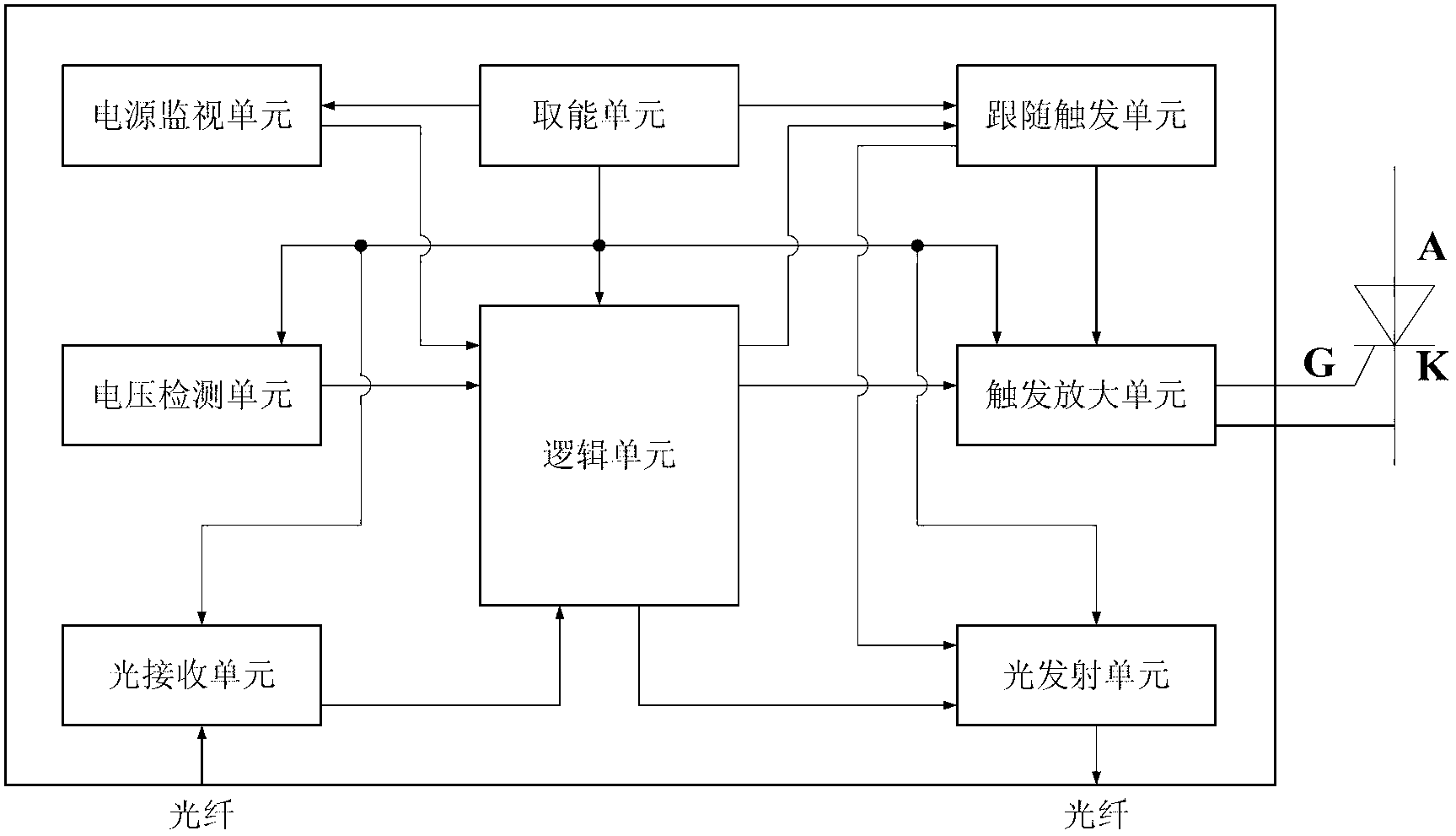
[0037] Such as figure 1 As shown, the present invention provides a thyristor switching capacitor valve group trigger system for switching the thyristor valve group. The thyristor valve group includes several thyristor units connected in series, and each thyristor unit consists of two thyristor units. Thyristors connected in antiparallel to each other; the trigger system includes an energy-taking unit, a logic unit, a power monitoring unit, a voltage detection unit, a light receiving unit, a follow-up trigger unit, a trigger amplification unit and a light emitting unit, wherein:

[0038] The energy-taking unit obtains the energy required to trigger the system to work from the high potential;

[0039] The power monitoring unit is connected to the energy harvesting unit, detects the energy harvesting voltage, and sends a fault signal to the l...


PUM


Abstract

The invention discloses a triggering system of a thyristor switched capacitor valve set. According to the triggering system of the thyristor switched capacitor valve set, an energy-taking unit obtains energy needed by the triggering system for operation from high potential, a power supply monitoring unit sends a fault signal to a logical unit when the obtained energy is not sufficient, a voltage detecting unit outputs a signal to the logical unit when detecting that the voltage of the positive electrode of the thyristor reaches a set value, the logical unit returns an optical pulse to a superior controlling unit when receiving the output signal of the voltage detecting unit, the logical unit controls a triggering amplifying unit to trigger turn-on of the thyristor when receiving a trigger optical pulse, the triggering amplifying unit triggers the normal turn-on of the thyristor in a controlling box of the logical unit, and a following triggering unit automatically triggers the turn-on when the turn-on of the thyristor delays. The triggering system of the thyristor switched capacitor valve set is reliable in operation, strong in anti-jamming capacity, free of the high-voltage isolation problem, particularly applicable to thyristor switched capacitor valve set triggering systems of a 35kV voltage class or over-35kV voltage classes, and capable of solving the triggering problem of the serial thyristor valve set.

Description

technical field [0001] The invention belongs to the application field of power electronics and power systems, in particular to a thyristor switching capacitor valve group trigger system. Background technique [0002] With the maturity of high-power power electronic technology and the needs of power system development, more and more power electronic devices have been applied to power systems. [0003] The group switching of capacitors was realized by mechanical circuit breakers in the early days, which is the mechanical switching capacitor (MSC); when the series thyristor valve group is applied to capacitor switching, the thyristor switching capacitor (TSC) appears. ). Compared with mechanical circuit breakers, the operating life of the thyristor is almost unlimited, and the switching time of the thyristor can be precisely controlled to reduce the inrush current and operating overvoltage during switching. [0004] The most critical technology in thyristor switching capacito...

Claims


Application Information

Patent Timeline
IPC IPC(8): H02J3/18
CPCY02E40/10
Inventor 刘磊陈赤汉李海英曹冬明丁勇张磊
Owner NR ELECTRIC CO LTD
Why Eureka
Try Eureka