
Pressure sensor dielectric medium isolation packaging structure and packaging method of same

A pressure sensor and medium isolation technology, applied in the field of sensors, can solve the problems of high cost, complex packaging process, complicated installation, etc., and achieve the effect of avoiding the process of filling silicone oil and reducing manufacturing costs.

Active Publication Date: 2013-08-21
MEMSENSING MICROSYST SUZHOU CHINA
View PDF12 Cites 31 Cited by
  • Summary
  • Abstract
  • Description
  • Claims
  • Application Information

AI Technical Summary

Problems solved by technology

[0005] The existing mainstream pressure sensor dielectric isolation packaging technology has many shortcomings such as complex packaging process, high cost, large volume, and complicated installation, so it is mainly used in the field of industrial control with high affordability

Method used


Image

  • Pressure sensor dielectric medium isolation packaging structure and packaging method of same
  • Pressure sensor dielectric medium isolation packaging structure and packaging method of same
  • Pressure sensor dielectric medium isolation packaging structure and packaging method of same

Examples


no. 1 approach

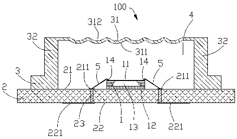
[0050] Please refer to figure 1 As shown, the pressure sensor medium isolation package structure 100 of the present invention includes a pressure sensor chip 1, a substrate 2 for carrying the pressure sensor chip 1, a bonding wire 5, and a pressure sensor chip fixed on the substrate 2 and surrounded by the pressure sensor chip 1. Peripheral cover body 3 . The pressure sensor chip 1 includes a pressure sensitive film 11 , a silicon substrate 12 , a back cavity 13 formed on the silicon substrate 12 , and an electrode 14 located on the silicon substrate 12 . The substrate 2 includes a front side 21 , a back side 22 opposite to the front side 21 , and a metallized hole 23 passing through the front side 21 and the back side 22 . In addition, the substrate 2 further includes inner pins 211 on the front side 21 and outer pins 221 on the back side 22 . The bonding wire 5 is connected to the electrode 14 of the pressure sensor chip 1 and the inner pin 211, and the metallized hole 23 ...

no. 2 approach

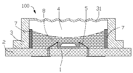
[0056] Please refer to figure 2 As shown, the difference between the pressure sensor medium isolation package structure 100 in the second embodiment of the present invention and the first embodiment is that the pressure sensor medium isolation package structure 100 also has a The cofferdam part 7 on the inner surface of the side wall 32 and the potting glue 8 located within the range of the cofferdam part 7 . The dam component 7 is located on the periphery of the pressure sensor chip 1 to limit the coverage of the encapsulant 8 . The potting glue 8 covers the pressure sensor chip 1 and the bonding wire 5 . The potting compound 8 has characteristics such as low shrinkage and small stress, such as silicon rubber, etc., and is used to protect the pressure sensor chip 1 and the bonding wire 5 . At the same time, the gas pressure in the airtight cavity 4 can be transmitted to the pressure sensitive membrane 11 through the potting glue 8 .

[0057] The cofferdam component 7 not ...

no. 3 approach

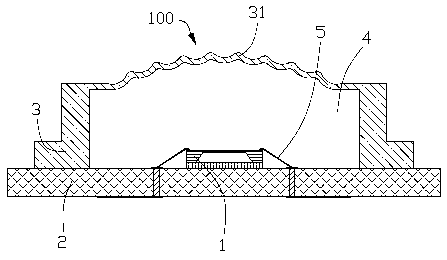
[0059] Please refer to image 3 As shown, the difference between the medium isolation packaging structure 100 of the pressure sensor in the third embodiment of the present invention and the first embodiment is that the top wall 31 of the cover body 3 is convex upward as a whole.


PUM


Abstract

The invention discloses a pressure sensor dielectric medium isolation packaging structure and a packaging method of the pressure sensor dielectric medium isolation packaging structure. The pressure sensor dielectric medium isolation packaging structure comprises a substrate, a cover body made of soft low-elasticity-modulus materials and a pressure sensor chip. The cover body and the substrate form an airtight cavity body together in order to accommodate the pressure sensor chip. When the pressure of a dielectric medium to be measured is acted on the cover body, the cover body deforms and accordingly compresses gas in the airtight cavity body to achieve balanced internal and external pressure. In the process, the dielectric medium to be measured is transmitted to a pressure sensitive membrane of the pressure sensor chip and accordingly the purpose that the pressure of pressure sensor chip and the pressure of the dielectric medium to be measured are separated is achieved. According to the pressure sensor dielectric medium isolation packaging structure and the packaging method of the pressure sensor dielectric medium isolation packaging structure, the pressure is transmitted by compressing the gas, and accordingly complex silicone oil filling procedures in a traditional silicone oil filling stainless steel packaging technology are avoided and manufacturing cost is greatly reduced.

Description

technical field [0001] The invention relates to a pressure sensor medium isolation package structure and a package method thereof, in particular to a low-cost pressure sensor medium isolation package structure and a package method for isolating a measurement medium, and belongs to the field of sensors. Background technique [0002] A pressure sensor is a transducer that converts a measured pressure signal into an electrical signal. It is currently widely used in various fields such as water conservancy, meteorology, medical treatment, industrial control, automobiles, aerospace, and consumer electronics. After years of technological progress, the pressure sensor has become one of the most mature technology, the most stable performance, the most widely used and the most cost-effective among all kinds of sensors. [0003] According to different working principles, pressure sensors can be mainly divided into piezoresistive, capacitive, resonant, piezoelectric, optical fiber and ...

Claims


Application Information

Patent Timeline
IPC IPC(8): G01L1/18G01L9/02
Inventor 陶永春梅嘉欣胡维李刚
Owner MEMSENSING MICROSYST SUZHOU CHINA
Learn More