
Manufacturing device and manufacturing method for light guide film

A technology for manufacturing devices and manufacturing methods, which is applied in the field of light-guiding film manufacturing devices, can solve problems such as limiting the thinning of light-guiding films, poor light transmittance, and poor light-guiding effects of light-guiding films, and achieves the improvement of thinness The effect of reducing the degree of thickness and reducing the thickness

Inactive Publication Date: 2013-08-14
HONG FU JIN PRECISION IND (SHENZHEN) CO LTD +1
View PDF5 Cites 5 Cited by
  • Summary
  • Abstract
  • Description
  • Claims
  • Application Information

AI Technical Summary

Problems solved by technology

[0003] However, the use of PET film as a carrier limits the further thinning of the light guide film
In addition, the light transmittance of the PET film itself is about 90%, so the light guide film inevitably reduces the light transmission by about 10%, resulting in poor light transmittance
Furthermore, the single surface of the light guide film is generally formed with a microstructure for scattering light, but the light guide effect of the light guide film with a single surface microstructure is not good.

Method used

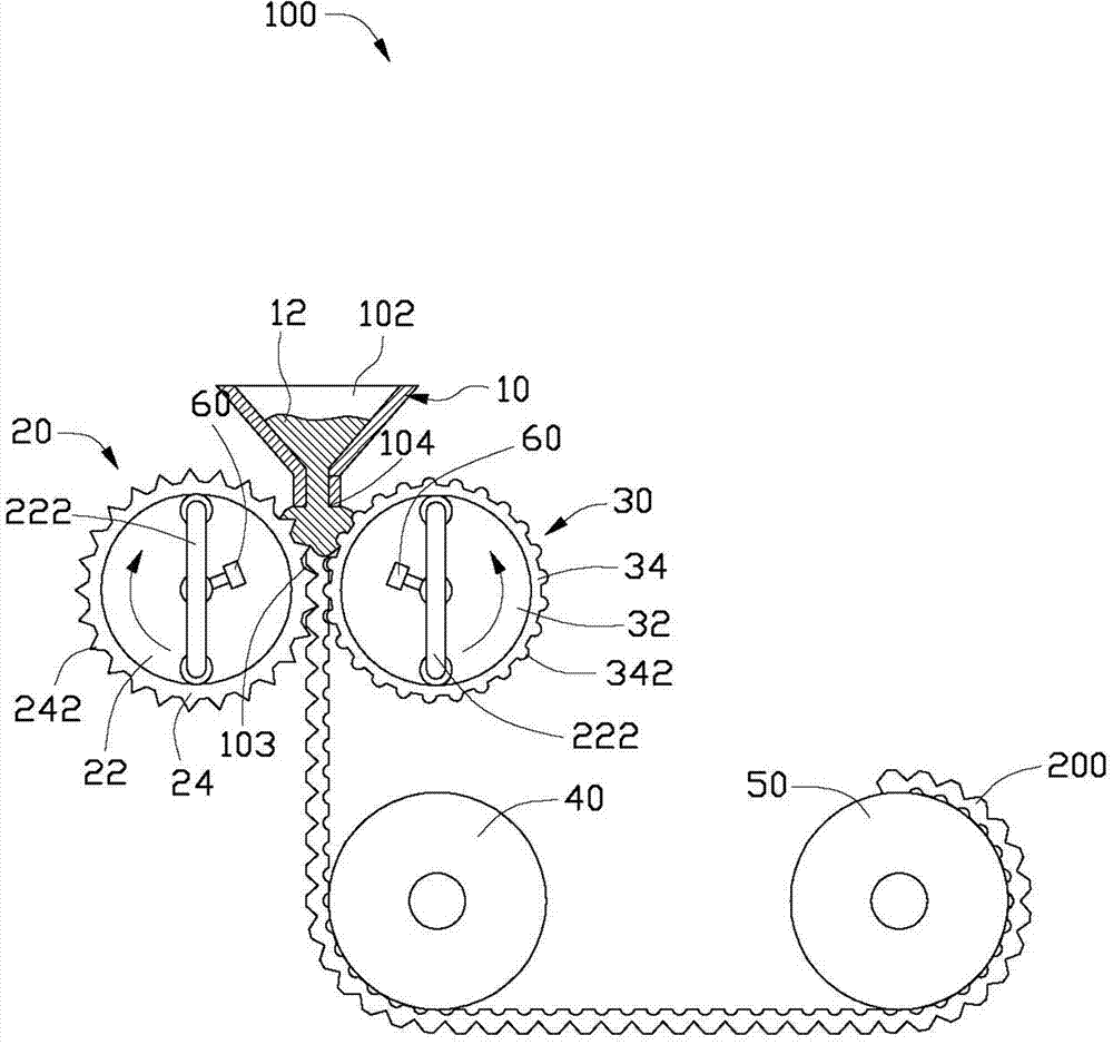
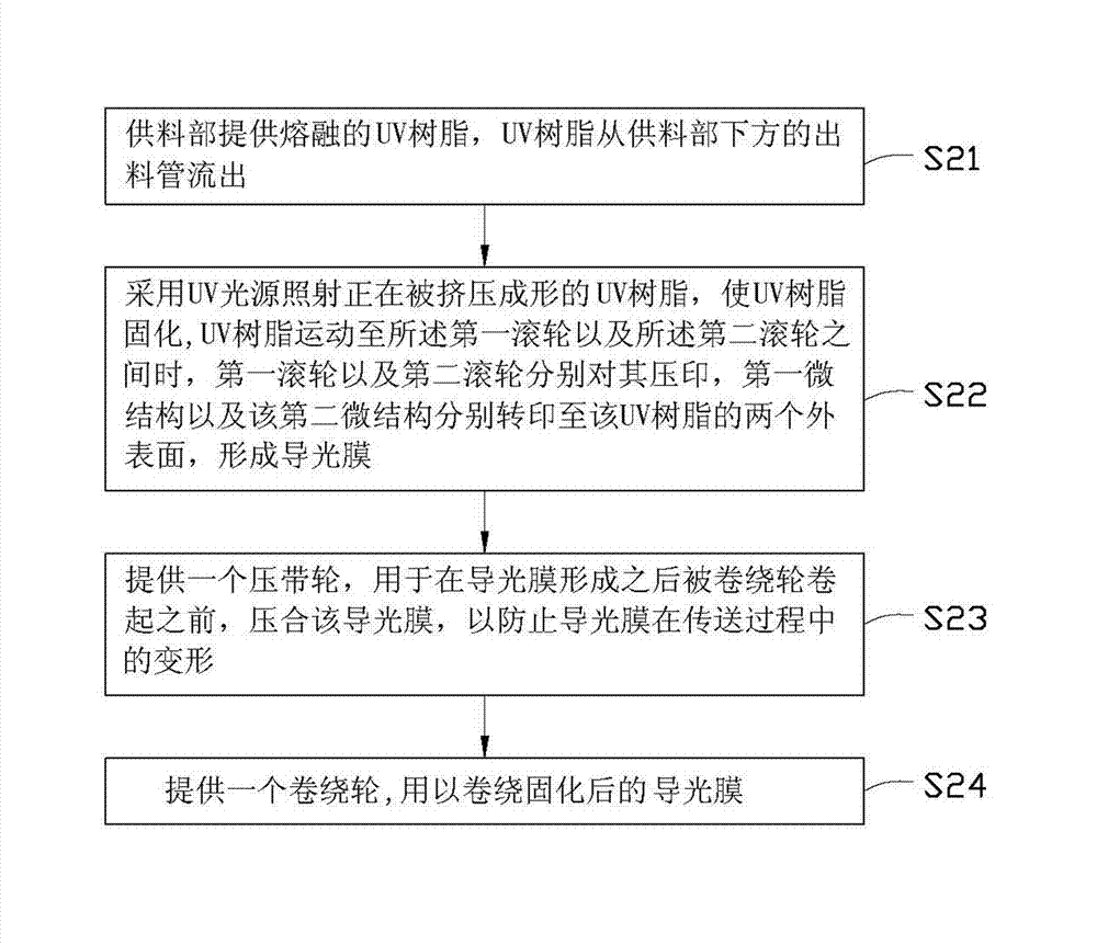
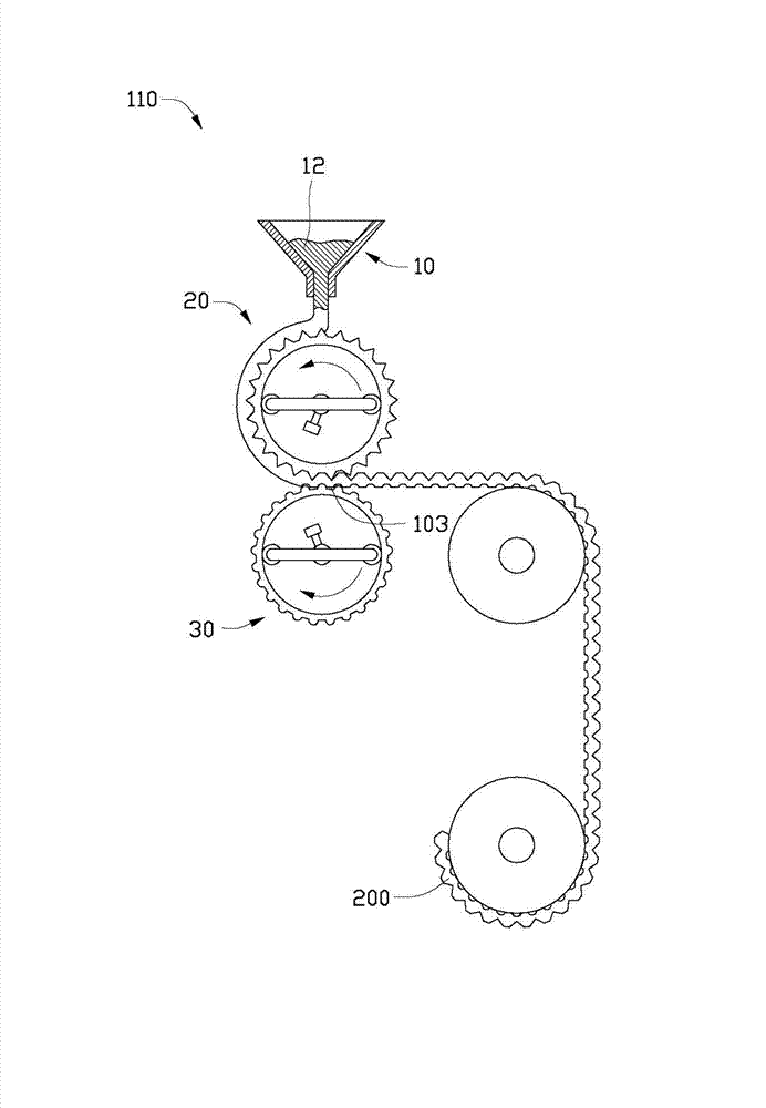

Image

  • Manufacturing device and manufacturing method for light guide film
  • Manufacturing device and manufacturing method for light guide film
  • Manufacturing device and manufacturing method for light guide film

Examples


Embodiment Construction

[0017] The present invention will be described in detail below in conjunction with the drawings.

[0018] See figure 1 , Shown is a schematic diagram of the light guide film manufacturing apparatus 100 according to the first embodiment of the present invention. The light guide film manufacturing apparatus 100 includes a feeder 10 (here is a reciprocating coating head, in other embodiments it can be Scraper), a first roller 20, a second roller 30, a pinch roller 40 and a winding wheel 50.

[0019] The feeding part 10 is used to supply the raw material for manufacturing the light guide film 200. In this embodiment, the raw material of the light guide film 200 is the UV resin 12 in a molten state. The feeding part 10 is roughly in the shape of a funnel, which includes a feeding port 102 and a corresponding discharging tube 104. The UV resin 12 enters the feeding part 10 from the feeding port 102 and flows out along the discharging tube 104.

[0020] The first roller 20 and the second r...


PUM

PropertyMeasurementUnit
transmittivityaaaaaaaaaa

Abstract

The invention relates to a manufacturing device for a light guide film. The manufacturing device comprises a material feeding part, a first rolling wheel, a second rolling wheel as well as at least one UV (Ultraviolet) light source arranged inside the first rolling wheel or the second rolling wheel, wherein the material feeding part is used for providing molten UV resin; the first rolling wheel and the second rolling wheel are oppositely arranged at a predetermined interval; a plurality of grooves are formed in the surface of the first rolling wheel; the second rolling wheel is provided with a screen-dot microstructure; the first rolling wheel and the second rolling wheel are used for extrusion moulding of the UV resin; and the UV light sources are used for solidifying the UV resin in extrusion moulding. The invention further relates to a manufacturing method for the light guide film.

Description

Technical field [0001] The invention relates to a light guide film manufacturing device and manufacturing method. Background technique [0002] At present, in the manufacture of light guide films, a UV (ultraviolet) resin is generally first coated on the surface of the PET film, and a microstructure pattern is transferred on the UV resin. After the transfer is completed, the PET film is irradiated with UV light to cure the UV resin on the surface of the PET film. [0003] However, the use of PET film as a carrier limits the further thinning of the light guide film. In addition, the light transmittance of the PET film itself is about 90%, so the light guide film inevitably reduces light transmission by about 10%, resulting in poor light transmittance. Furthermore, the single surface of the light guide film is generally formed with a microstructure for scattering light, but the light guide effect of the light guide film with a single-sided microstructure is not good. Summary of th...

Claims


Application Information

Patent Timeline
Patent Type & Authority Applications(China)
IPC IPC(8): G02B6/00B32B38/14
Inventor 许嘉麟
Owner HONG FU JIN PRECISION IND (SHENZHEN) CO LTD
Learn More