Mounting method for steel anchor beam of cable-stayed bridge and assembly jig and cable bent tower mounting platform used in method
A cable-stayed bridge steel and installation platform technology, applied in the direction of bridges, bridge construction, erection/assembly of bridges, etc., can solve the problems of high operation difficulty, high risk, complicated procedures, etc., so as to reduce construction costs, save construction time, improve The effect of installation accuracy
- Summary
- Abstract
- Description
- Claims
- Application Information
AI Technical Summary
Problems solved by technology
Method used
Image
Examples
Embodiment 1
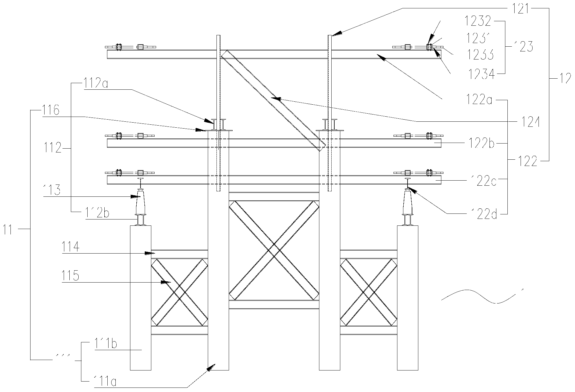
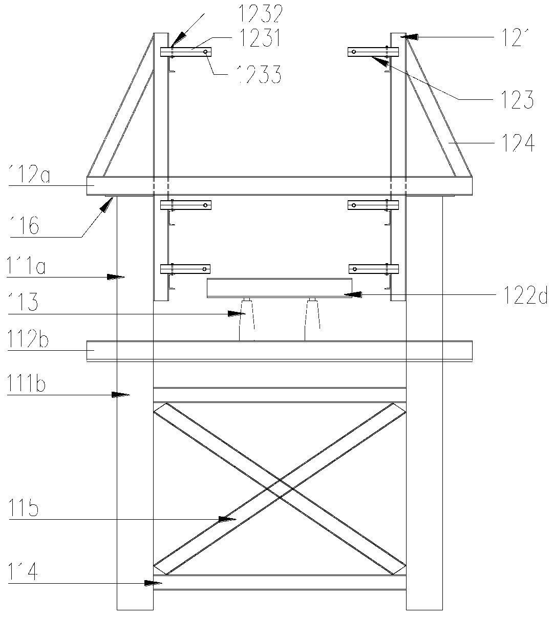
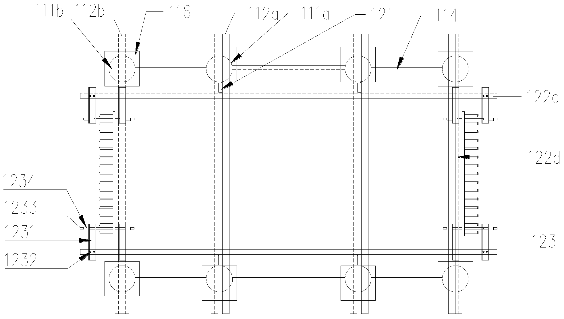
[0052] Please refer to Figure 1-3 , is a schematic structural view of the cable-stayed bridge steel anchor beam assembled tire frame 1 in the present invention, and the assembled tire frame 1 includes a load-bearing structure 11 and a positioning structure 12 .
[0053]The load-bearing structure 11 includes a steel pipe column assembly 111 and is used to support the assembled components (that is, the steel corbel 3 and the steel anchor beam 4, see Figure 5A and Figure 5B ) of the load-bearing beam 112 .
[0054] The steel pipe upright assembly 111 includes four middle steel pipe uprights 111a arranged in the middle of the tire frame 1 and distributed in a rectangular shape and four side steel pipe uprights 111b arranged on both sides of the tire frame 1 . Four middle steel pipe columns 111a and four side steel pipe columns 111b jointly constitute the rectangular frame structure of the tire frame 1, wherein, the middle steel pipe columns 111a are higher than the side steel...
Embodiment 2
[0058] Please refer to Figure 4 , Figure 7A , Figure 7B and Figure 7C , is the schematic structural view of the cable-stayed bridge steel anchor beam tower installation platform 2 in the present invention, the installation platform 2 includes two H-shaped brackets connected front and rear, which are respectively the front H-shaped bracket 2a and the rear H-shaped bracket 2b, so that Both the front H-shaped bracket 2a and the rear H-shaped bracket 2b include two parallel columns 21 and a beam 22 connected between the columns; further, the front H-shaped bracket 2a also includes The distribution beam 23, three jacking brackets 24 evenly arranged between the distribution beam 23 and the cross beam 22 and the jack 25 arranged on the upper end of the column 21 and directed to the axis of symmetry of the front H-shaped bracket.
[0059] Described installation platform 2 is usually used in pairs, is arranged on the two ends of installed steel corbel 31, is positioned for next ...
Embodiment 3
[0061] Below the installation method of the cable-stayed bridge steel anchor beam that utilizes above-mentioned steel anchor beam to assemble tire frame 1 and the steel anchor beam cable tower installation platform 2 of the present invention to be further described, its steps are as follows:
[0062] (1) Set up the steel anchor beam assembly tire frame 1 as described in Embodiment 1;
[0063] (2) Lift the steel anchor beam 4 to the first load-bearing beam 112a of the tire frame 1 for positioning, such as Figure 6A shown;
[0064] (3) hoisting the steel corbel 3 onto the fourth positioning beam 122d on the tire frame 3, and positioning it with the steel anchor beam 4 in the step (2), so that the steel corbel 3 is supported on the steel anchor beam 4, use the jack 113 to adjust the elevation and level of the steel corbel 3, and then use the connecting bolt 5 between the steel anchor beam 4 and the steel corbel 3 to fix the two screws, and repeat Measure the elevation and leve...
PUM
 Abstract
Description
Claims
Application Information
 - R&D
- Intellectual Property
- Life Sciences
- Materials
- Tech Scout
- Unparalleled Data Quality
- Higher Quality Content
- 60% Fewer Hallucinations
Browse by: Latest US Patents, China's latest patents, Technical Efficacy Thesaurus, Application Domain, Technology Topic, Popular Technical Reports.
© 2025 PatSnap. All rights reserved.Legal|Privacy policy|Modern Slavery Act Transparency Statement|Sitemap|About US| Contact US: help@patsnap.com


