
Parallel-central-valve type automobile brake master cylinder

A technology of automobile brake and master cylinder, which is applied in the direction of hydraulic brake transmission device, etc., can solve the problems of shortening the axial distance of the brake master cylinder, not being able to fully realize independent work, and easy damage, etc., to shorten the stroke of the brake push rod , Shorten the braking reaction time, the effect of quick response

Inactive Publication Date: 2015-04-08
JILIN UNIV
View PDF12 Cites 3 Cited by
  • Summary
  • Abstract
  • Description
  • Claims
  • Application Information

AI Technical Summary

Problems solved by technology

[0006] The purpose of the present invention is to provide a parallel center valve brake master cylinder, which overcomes the shortcomings of the traditional compensation hole brake master cylinder, such as impermanence and easy damage, and solves the inability of the two circuits of the double-cylinder serial brake master cylinder. Completely realize independent work, the leakage of one pipeline will affect the push rod stroke and the establishment of oil pressure of the other pipeline. At the same time, it can shorten the axial distance of the brake master cylinder and reduce the space occupied by the engine compartment. And can be well suited for automotive anti-lock braking systems

Method used


Image

  • Parallel-central-valve type automobile brake master cylinder
  • Parallel-central-valve type automobile brake master cylinder
  • Parallel-central-valve type automobile brake master cylinder

Examples


Embodiment Construction

[0055] The invention will be described in detail below in conjunction with the accompanying drawings.

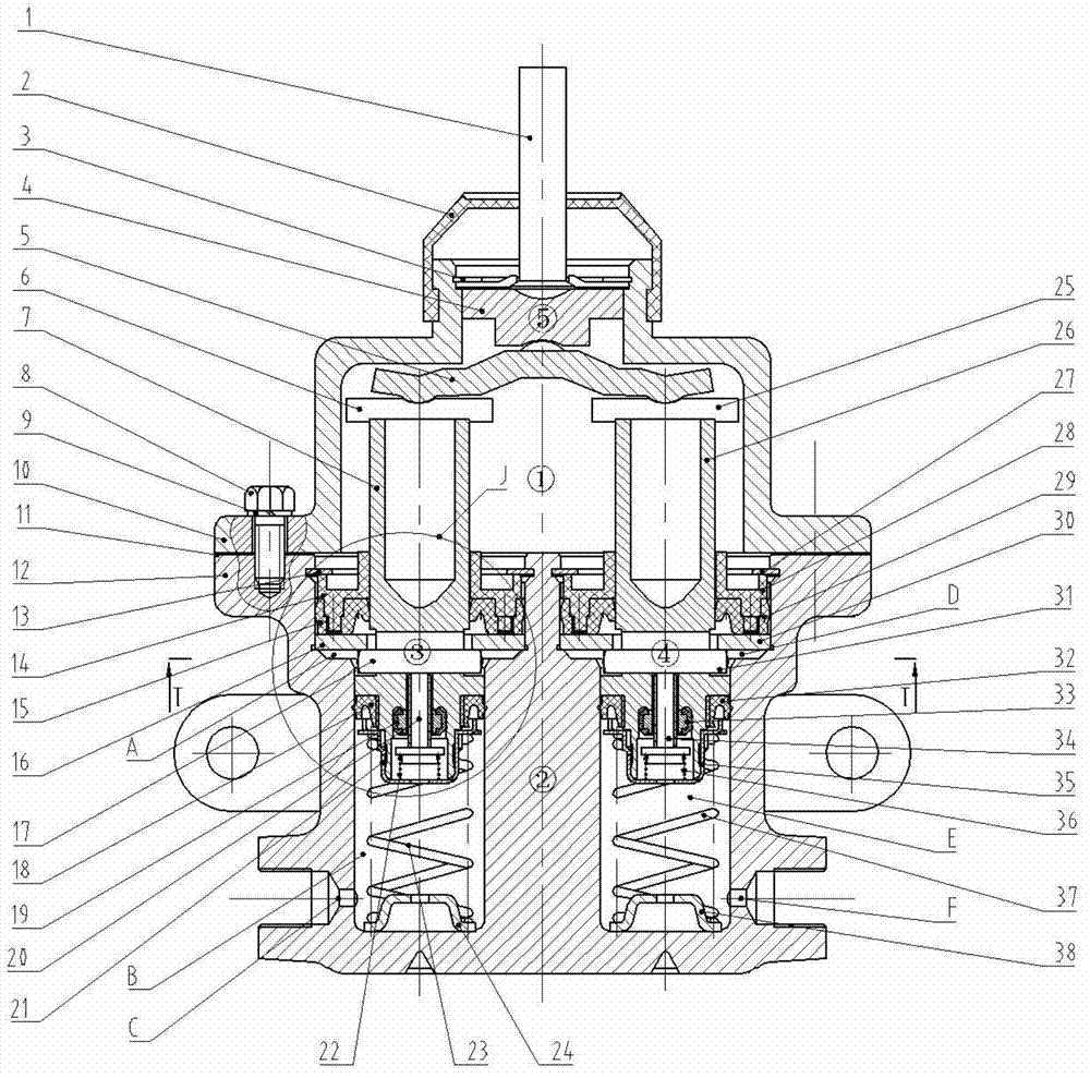
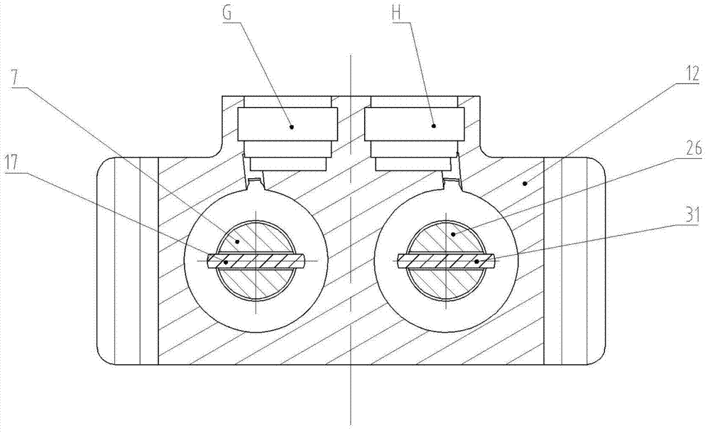
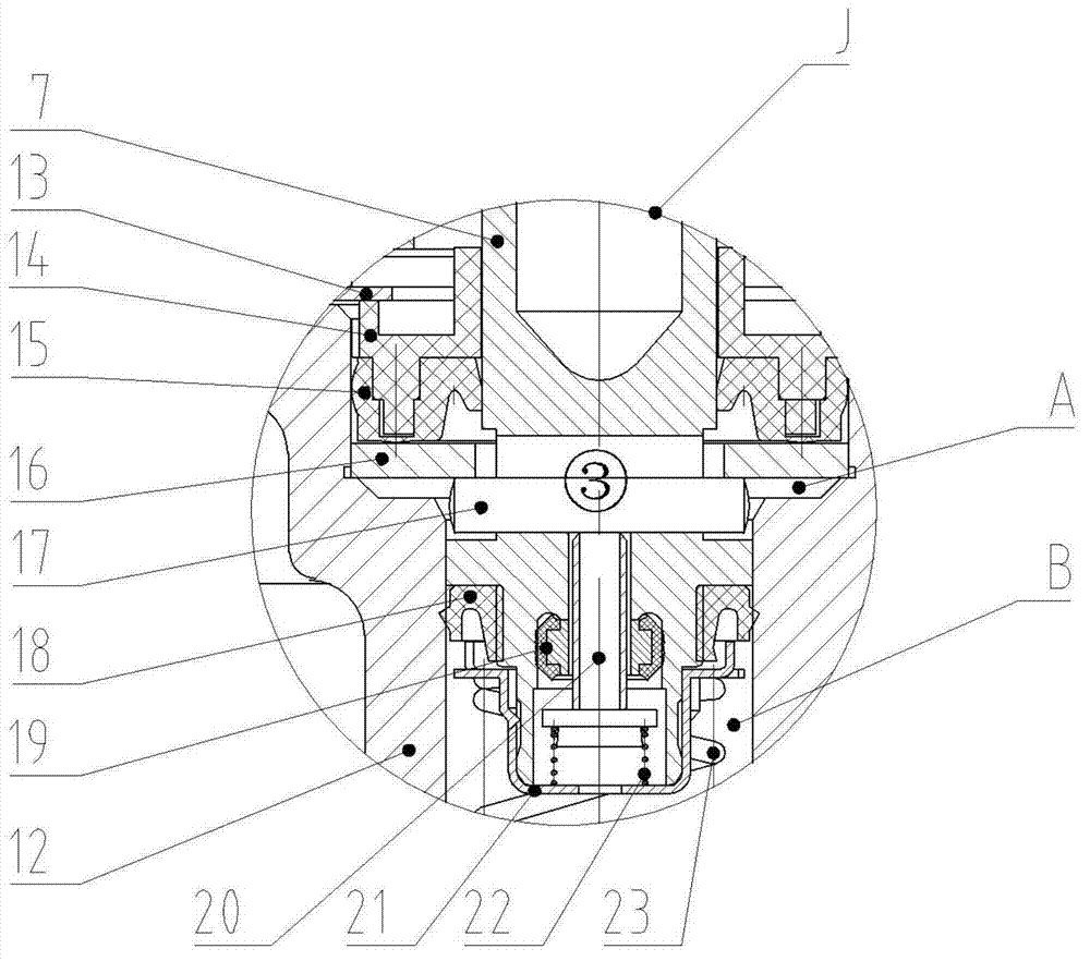
[0056] figure 1 It is the main cross-sectional view of the present invention, and it can be seen that a parallel central valve type automobile brake master cylinder of the present invention comprises cylinder upper part ①, cylinder body bottom ②, left master cylinder ③, right master cylinder ④ and force transmission mechanism ⑤, wherein , the force transmission mechanism ⑤ is located in the upper part of the cylinder body ①, and the thrust from the push rod and vacuum booster is transmitted to the left and right master cylinders ③ and ④ paralleled by the push rod 1 through the push rod 1; the left master cylinder ③ and the right master cylinder ④Located in the lower part of the cylinder body ②, it converts and amplifies the mechanical thrust transmitted by the push rod 1 into hydraulic pressure, and then transmits it to each wheel cylinder and wheel brake through the oil out...


PUM


Abstract

The invention discloses a parallel-central-valve type automobile brake master cylinder. The cylinder comprises a cylinder body upper portion, a cylinder body lower portion, a left master cylinder, a right master cylinder and a force transmitting mechanism, the force transmitting mechanism is arranged inside the cylinder body upper portion and transfers thrust coming from a push rod and a vacuum booster to the left master cylinder and the right master cylinder which are parallel to each other in a left-and-right mode by the push rod, the left master cylinder and the right master cylinder are basically identical in structure, are symmetrically arranged inside the cylinder body lower portion, convert and amplify the mechanical thrust transferred by the push rod into a hydraulic force and then transmit the hydraulic force through an oil outlet by a brake pipeline to all wheel cylinders and wheel brakes, and the cylinder body upper portion is fixedly connected with the cylinder body lower portion. According to the automobile brake master cylinder, the dual parallel cylinder structure is adopted, two brake hydraulic loops work independently, the fact that oil pressure of one cylinder can not be established has little influence on the other cylinder, the longitudinal distance of the brake master cylinder can be greatly shortened, the requirement for the engine compartment space is reduced, classes of parts are reduced, the machining cost is reduced, and the brake master cylinder is good in generality and broad in application prospect.

Description

technical field [0001] The invention belongs to the technical field of automobile brakes, in particular to a parallel central valve type automobile brake master cylinder used for automobile brake systems, especially anti-lock brake systems. Background technique [0002] The brake master cylinder is a key component in the automobile braking system. Its function is to push the piston in the master cylinder to move forward through the action of the pedal force, so that the brake master cylinder generates hydraulic pressure, and sends hydraulic pressure to the entire automobile braking system through the oil outlet hole of the master cylinder, so as to realize the brake of the car. brake. [0003] The common brake master cylinder has a compensation hole structure, see Chinese patents ZL201120370655.X, ZL200720113843.8 and ZL201120496915.8. When not working, the working chamber of the master cylinder communicates with the oil cup through the compensation hole in the cylinder wa...

Claims


Application Information

Patent Timeline
Patent Type & Authority Patents(China)
IPC IPC(8): B60T11/16
Inventor 许洪国熊钊郑根祥
Owner JILIN UNIV
Learn More