
Gantry crane

A gantry crane and gantry technology, applied in the direction of cranes, trolley cranes, load hanging components, etc., can solve the problems of reduced lifting height of spreaders, inability to meet use requirements, and increased crane weight.

Active Publication Date: 2013-02-13
NUCLEON XINXIANG CRANE
View PDF6 Cites 7 Cited by
  • Summary
  • Abstract
  • Description
  • Claims
  • Application Information

AI Technical Summary

Problems solved by technology

This causes the following problems in the existing gantry cranes: the vertical distance between the main girder and the spreader is large, and the lifting height of the spreader is correspondingly reduced, which cannot meet the requirements of use. In order to meet the requirements of use, the column has to be added The height of the corresponding column also needs to be increased, which will increase the self-weight of the crane; at the same time, the hook is generally set in the middle of the main beam. The weight of the main beam and column is increased, which makes the crane consume a lot of power when it is working

Method used


Image

  • Gantry crane
  • Gantry crane
  • Gantry crane

Examples


Embodiment Construction

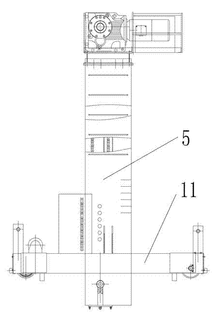
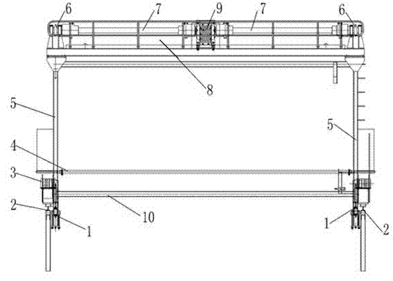
[0017] An example of a gantry crane Figure 1~3 As shown: it includes two guide rails 2 arranged side by side at intervals from left to right and the guiding direction extends along the front and rear directions. The two guide rails 2 are equipped with a gantry for guiding and moving. 3 and a displacement detection device for detecting the moving stroke of the gantry. The gantry includes uprights 5 which are respectively guided and moved and assembled on corresponding guide rails 2 and a main girder 8 bridging the upper ends of the two uprights 5 . The two ends of the beam 10 are assembled on the two uprights 5 through the corresponding guide structure to guide and move in the up and down direction. The guide structure includes a guide with the slots on the two uprights 5 facing opposite and the guiding directions extending in the up and down direction. The left and right ends of the suspension beam 10 are respectively guided and inserted into the guide grooves of the corresp...


PUM


Abstract

The invention relates to a gantry crane. The gantry crane comprises a gantry, wherein the gantry comprises two columns and a main beam; the two columns are arranged left and right at intervals; the main beam is bridged at the upper ends of the two columns; the gantry crane also comprises a hanging beam with length extending in the left-right direction; the hanging beam is used for installing corresponding hangers; the two ends of the hanging beam are respectively assembled on the two columns via corresponding guide structures by moving vertically in a guided manner; the gantry is provided with one or at least two transmission chains connected with the hanging beam through transmission so as to drive the hanging beams to go up and down; and the gantry is also provided with a chain wheel driving mechanism for driving one transmission chain to make cyclic action or all the chains to make cyclic action synchronously. The gantry crane provided by the invention can reduce the vertical distances between the main beam and the corresponding hangers.

Description

technical field [0001] The present invention relates to lifting equipment, in particular to gantry cranes. Background technique [0002] In the existing galvanizing production process, gantry cranes are often used. The gantry cranes are installed next to the corresponding galvanizing pools, and the steel structures that need to be galvanized are hoisted into the galvanizing pools by the gantry cranes for galvanizing. craft. Existing gantry cranes include a gantry. The gantry includes two uprights arranged at intervals on the left and right and a main girder bridged at the upper ends of the two uprights. An electric hoist is installed, and a hook is hung under the electric hoist through a wire rope, and the hook is connected to the spreader through a corresponding rope. This causes the following problems in the existing gantry cranes: the vertical distance between the main girder and the spreader is large, and the lifting height of the spreader is correspondingly reduced, w...

Claims


Application Information

Patent Timeline
Patent Type & Authority Applications(China)
IPC IPC(8): B66C19/00B66C6/00
Inventor 孙石头马喜朋杨孟虎王雅靖尹海超袁永力李士祥
Owner NUCLEON XINXIANG CRANE
Learn More