
Metal sheet machining centering device and metal sheet machining centering method

A metal sheet and processing equipment technology, applied in the field of metal sheet processing centering devices, can solve the problems of inconvenient on-line adjustment, low, unreachable, difficult to find out the exact corresponding relationship, etc., achieve reasonable structure, improve the scope of application, Easy-to-use effects

Active Publication Date: 2014-12-17
GUANGXI LIUZHOU YINHAI ALUMINUM IND
View PDF6 Cites 0 Cited by
  • Summary
  • Abstract
  • Description
  • Claims
  • Application Information

AI Technical Summary

Problems solved by technology

However, this device is only suitable for the centering of metal plates with a thickness greater than a certain value. For metal plates with small or thinner deformation resistance, if this device is still used to center such metal plates, it will be difficult due to the clamping pressure value. If it is too low, the action threshold of the pressure sensor has not been reached, causing the hydraulic cylinder to work all the time and causing the metal sheet to be severely clamped and deformed by overclamping, which will have a negative impact on the quality of the finished product of the metal sheet
The traditional solution is: adjust the working pressure of the hydraulic cylinder or the action threshold of the pressure relay according to the thickness of the metal sheet. The thinner the metal sheet, the lower the working pressure of the hydraulic cylinder or the action threshold of the pressure relay. To avoid the deformation of the metal sheet by clamping, its disadvantage is that it is difficult to find out the exact corresponding relationship, and it is not convenient for online adjustment

Method used


Image

  • Metal sheet machining centering device and metal sheet machining centering method
  • Metal sheet machining centering device and metal sheet machining centering method
  • Metal sheet machining centering device and metal sheet machining centering method

Examples


Embodiment Construction

[0043] The present invention will be described in further detail below in conjunction with accompanying drawing embodiment:

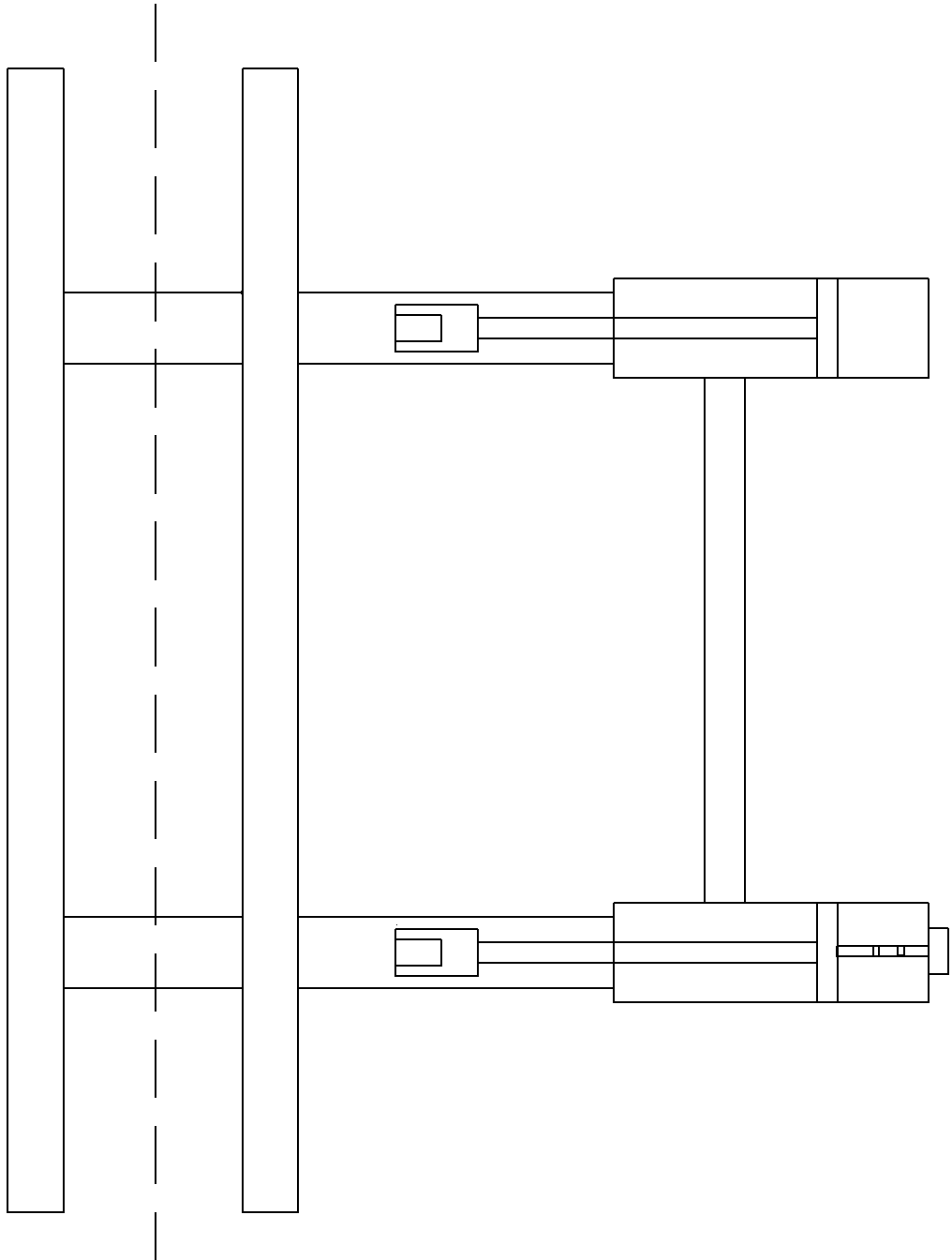
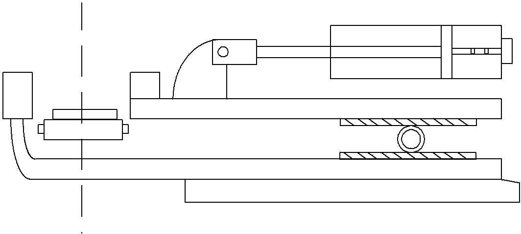
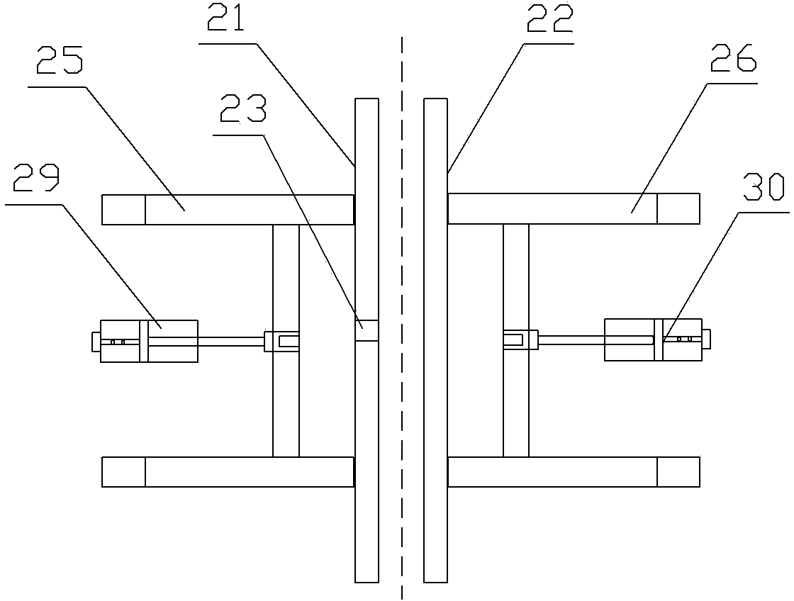
[0044] image 3 with Figure 4The shown centering device for sheet metal processing includes two side guide plates symmetrically arranged in parallel with a straight line as the center line, that is, a left guide plate 21 and a right guide plate 22. The left guide plate 21 is provided for The pressure relay 23 for detecting the size of the clamping force, each side guide plate is fixedly installed on one end of a movable support, and the other end of the movable support is movably connected with a hydraulic cylinder with a displacement sensor, that is, the right guide plate 22 is installed on the On the right support 26, the right support 26 is contained on the right guide rail 28, and the right hydraulic cylinder 30 is movably connected with the right support 26, and the left side guide plate 21 is contained on the left support 25, and the left suppor...


PUM


Abstract

The invention discloses a metal sheet machining centering device and a metal sheet machining centering method. The metal sheet machining centering device comprises two side guide plates, pressure relays, a metal detector, a laser tachometer and the like. The two side guide plates are symmetrical with each other along a straight center line and are parallelly opposite to each other, the pressure relays are arranged on the side guide plates, each side guide plate is fixedly mounted at one end of a movable support, each movable support is connected with a hydraulic cylinder with a displacement sensor, the displacement sensor of each hydraulic cylinder is electrically connected with a controller, and the metal detector is used for detecting the length of a metal sheet. The metal sheet machining centering method includes a step of enabling the two side guide plates to work simultaneously to respectively push and center the metal sheet and a step of enabling the two side guide plates to individually work to respectively push and center the metal sheet according to the thickness and the length of the metal sheet. Compared with the prior art, the metal sheet machining centering device and the metal sheet machining centering method have the advantage that the problem that metal sheets with low deformation resistance or thin metal sheets cannot be centered by an existing centering device is solved.

Description

technical field [0001] The invention belongs to the technical field of metal material processing, and in particular relates to a metal plate processing centering device and method. Background technique [0002] When thin metal plates are rolled, cut to length or cut to length, it is often necessary to center the metal plates with a centering device installed before and after the rolling mill or scissors, so that the center line of the metal plate is aligned with the rolling center line. Overlapping ensures good symmetry of the metal sheet in the subsequent processing process, so as to improve the dimensional control accuracy of the metal sheet and the stability of the processing process. At present, among the commonly used devices for centering metal sheets, there is a type of centering device with parallel side guides, such as figure 1 with figure 2 Shown: This centering device includes two sets of upper push rods and lower push rods respectively arranged in parallel on ...

Claims


Application Information

Patent Timeline
Patent Type & Authority Patents(China)
IPC IPC(8): B21B39/14
Inventor 许磊庞彦国蒋婷
Owner GUANGXI LIUZHOU YINHAI ALUMINUM IND
Learn More