
Adaptive quick focusing device and method for optical camera

An optical camera and self-adaptive technology, which is applied in the field of aerospace optical remote sensors, can solve the problems that the focusing effect depends on the richness, the imaging conditions are high, and the focus cannot be automatically adjusted, so as to reduce the number of mechanical movements and improve the focusing accuracy , Reduce the effect of focusing calculation

Inactive Publication Date: 2013-08-07
CHINA ACADEMY OF SPACE TECHNOLOGY
View PDF3 Cites 12 Cited by
  • Summary
  • Abstract
  • Description
  • Claims
  • Application Information

AI Technical Summary

Problems solved by technology

In our country, before the satellite is launched, digital or ground physical simulation and test methods are usually used to obtain the estimated value of the best focal plane position of the optical camera during the orbit phase, and the imaging plane is preset at the focal plane, but it cannot be based on On-orbit adaptive auto-focusing in different space environments
The existing on-orbit focusing technology in China also has a method of downloading the image data to the ground. After multiple image data interpretations are performed manually, the focus control information is uploaded to realize the focus judgment and focus adjustment of the on-orbit camera. It cannot automatically adjust the focus. The focus effect depends on the richness of the imaging target details. It has high requirements on the imaging conditions and the focus speed is slow.

Method used


Image

  • Adaptive quick focusing device and method for optical camera
  • Adaptive quick focusing device and method for optical camera
  • Adaptive quick focusing device and method for optical camera

Examples


Embodiment Construction

[0031] The invention is suitable for an optical camera whose image surface is adjusted back and forth along the optical axis direction to realize the focusing function.

[0032] According to Shannon's information theory, when the probability of an event is smaller, its prior uncertainty is greater and the amount of self-information contained is greater. The total number of pixels in the image plane of the CCD optical camera is a constant l×m, which defines the gray value i in the image (i=0,1,2,…2 k -1, k is the number of quantization bits, for example, k=8, the gray value range is 0~255) The total number of pixels corresponding to N is N i , The frequency that appears in the image is definition:

[0033] H = - X 0 2 k - 1 p ( i ) lg p ( i )

[0034] when At the smallest hour, the image is in focus and the image is clearest.

[0035] H = - X 0 2 k - 1 N i l X m lg N i l X m ...


PUM


Abstract

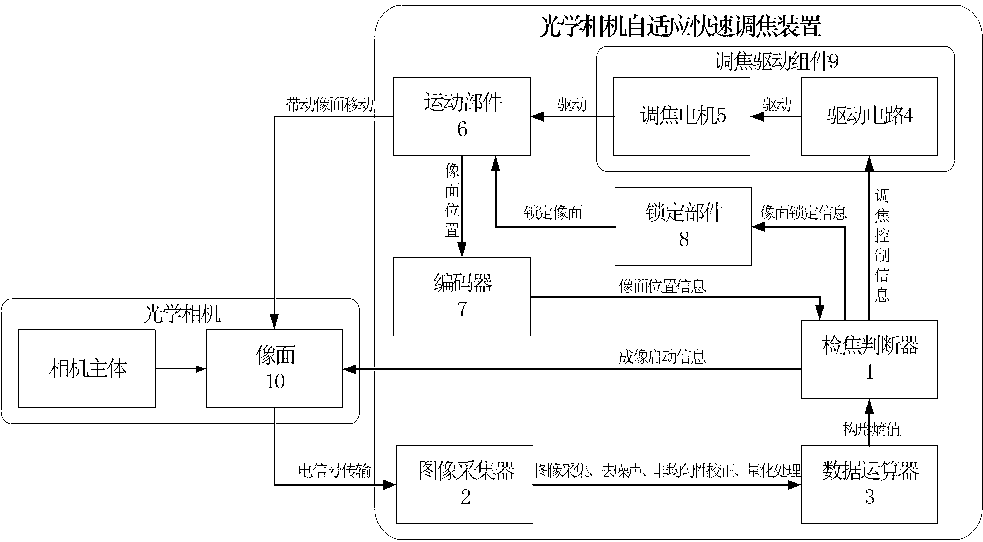
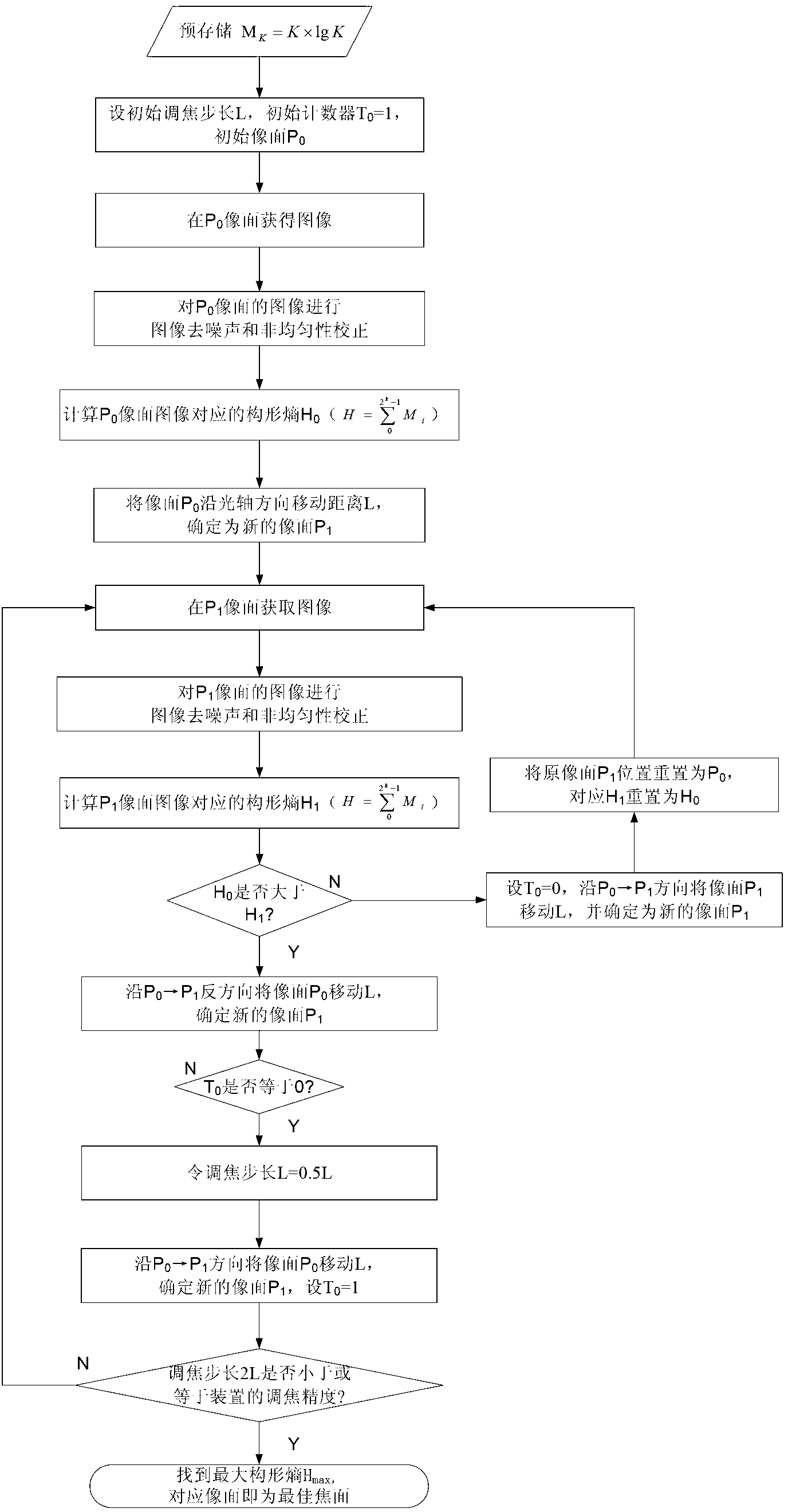
The invention discloses an adaptive quick focusing device for an optical camera. The adaptive quick focusing device comprises a focus detector (1), an image collector (2), a data arithmetic unit (3), a focusing drive component (9) and an encoder (7), wherein the encoder (7) is used for acquiring the position of an image surface (10) of the optical camera; the image collector (2) is used for acquiring a quantized image; the data arithmetic unit (3) is used for calculating a configuration entropy of the image; and the focus detector (1) is used for calculates configuration entropies of images at two different positions and sending focusing information to the focusing drive component (9) according to a result to drive the image surface (10) of the optical camera to reach the position of the maximum configuration entropy. An adaptive quick focusing method for the optical camera comprises the following steps of comparing the configuration entropies of images formed by the image surface (10) of the optical camera at two different positions, adjusting the moving direction according to the comparison result, and taking the position of the maximum configuration entropy of the image as the focusing position of the image surface (10) of the optical camera. The focusing speed is high, the focusing accuracy is high, and the requirement of weak contrast objects on space remote sensing is met.

Description

Technical field [0001] The invention belongs to the field of aerospace optical remote sensors, and relates to an optical camera self-adaptive fast focusing device and a corresponding method, which are used for on-track automatic focusing of the optical camera. Background technique [0002] The development of high spatial resolution optical remote sensors has always been an important part of human space technology, and high image quality is an important technical indicator of aerospace optical remote sensors. The optical camera will experience acceleration and violent vibration at the moment of launch. There is a huge pressure difference inside and outside the load compartment. Factors such as the sun and the earth’s radiation make the entire star heated unevenly. The space orbital atmospheric pressure changes with altitude. This series of temperature, Factors such as pressure and vibration will cause changes in the optical parameters such as the radius of curvature, surface shape...

Claims


Application Information

Patent Timeline
Patent Type & Authority Applications(China)
IPC IPC(8): H04N5/232
Inventor 郭玲华曹桂兴刘乃金邓峥李聪顾伟琪
Owner CHINA ACADEMY OF SPACE TECHNOLOGY
Learn More