A multi-storey building ventilation and air conditioning wall

A multi-storey building and wall technology, applied in buildings, building components, air-conditioning systems, etc., can solve problems such as the temperature and humidity are not considered, the temperature and humidity cannot be reached, and the heat exchange is insufficient, so as to achieve low manufacturing cost, The effect of beautifying the building appearance and saving internal space

Inactive Publication Date: 2016-01-06
JIANGXI UNIV OF SCI & TECH
View PDF8 Cites 1 Cited by
  • Summary
  • Abstract
  • Description
  • Claims
  • Application Information

AI Technical Summary

Problems solved by technology

The second design is simple and rough. It only considers the use of air to exchange heat with the water surface to realize the functions of heat exchange, humidification and ventilation. However, the air flow, temperature and humidity are not considered.
The third one uses interlayer, metal plate heat exchange and shaft effect to achieve wall ventilation. Such heat exchange is obviously insufficient and cannot meet the temperature and humidity requirements required by people.

Method used


Image

  • A multi-storey building ventilation and air conditioning wall
  • A multi-storey building ventilation and air conditioning wall

Examples


Embodiment Construction

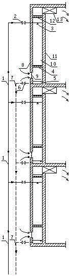
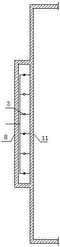
[0024] Such as figure 1 with figure 2 As shown, an example of a multi-story building ventilation and air-conditioning wall is provided with one or more building ventilation and air-conditioning walls on each floor. The building ventilation and air-conditioning wall includes a water supply device and a heat exchange wall, and the water supply device includes The water supply pipe 1, the flow regulating valve 2, the spray device 3, the water supply pipe 1 is provided with a flow throttle valve 2, and the spray device 3 is in communication with the water supply pipe 1; the heat exchange wall includes a thermal insulation outer Wall 8, thermal insulation inner wall 11, filter guide sheet 4, air inlet 9, ventilation and heat exchange interlayer 10, activated carbon filter layer 12 and induced blower 13, the gap between the thermal insulation outer wall 8 and the thermal insulation inner wall 11 is for ventilation

[0025] The thermal interlayer 10, further speaking, the width of the ...


PUM


Abstract

The invention discloses a ventilated air conditioning wall for a multi-storey building. The ventilated air conditioning wall comprises a water supply device and a heat exchange wall, wherein the water supply device comprises a water supply pipe, a flow regulating valve and a spray device, the flow regulating valve is arranged on the water supply pipe, and the spray device is communicated with the water supply pipe; the heat exchange wall comprises an external thermal insulating wall, an internal thermal insulating wall, a filtering drainage piece, an air inlet, a ventilated heat exchange interlayer, an activated carbon filtering layer and an air induced feeder, a gap between the external thermal insulating wall and the internal thermal insulating wall serves as the ventilated heat exchange interlayer, the activated carbon filtering layer and the filtering drainage piece are arranged in the ventilated heat exchange interlayer, the air inlet is arranged on the external thermal insulating wall, and the air induced feeder is arranged in the internal thermal insulating wall; the spray device is arranged in the ventilated heat exchange interlayer, and located between the activated carbon filtering layer and the filtering drainage piece; and the part, below the air inlet, of the ventilated heat exchange interlayer serves as a water return pool, and a water return pipe is communicated with the water return pool through a water return regulating valve. According to the invention, air is subjected to heat exchange and humidification through spraying cool water to an inner cavity of a wall in summer and spraying hot water to the inner cavity of the wall in winter, and then the air is fed indoors so as to achieve the purpose of ventilated air conditioning.

Description

Technical field [0001] The invention relates to the field of building ventilation technology and air conditioning, in particular to an air-conditioning wall that uses cold water in summer and hot water in winter to achieve ventilation and air-conditioning purposes, in particular to a multi-storey building with a spray device that fully exchanges heat through phase changes Ventilated air-conditioning wall. Background technique [0002] Existing air-conditioning equipment not only occupies land, the cost of air-conditioning equipment is relatively high, but also the installation of the equipment is relatively abrupt, which affects the appearance of the building; on the other hand, refrigerants such as Freon are likely to cause environmental pollution. [0003] Nowadays, many people build air-conditioning and ventilating walls based on the characteristics of the walls. For example, the invention patent "An evaporative cooling module ventilated exterior wall" with publication number CN...

Claims


Application Information

Patent Timeline
Patent Type & Authority Patents(China)
IPC IPC(8): E04B2/00E04B1/74F24F6/02F24F5/00
CPCY02B30/54
Inventor 蒋达华
Owner JIANGXI UNIV OF SCI & TECH
Why Eureka
Try Eureka