
Multi-flow-state reaction device

A fluid reaction and tank technology, applied in the field of multi-fluid reaction devices, can solve problems affecting the working efficiency of the agitator, and achieve the effects of simple and efficient heat exchange components, low energy loss, and improved adaptability

Active Publication Date: 2018-01-26
江苏和诺凯机械制造有限公司
View PDF9 Cites 2 Cited by
  • Summary
  • Abstract
  • Description
  • Claims
  • Application Information

AI Technical Summary

Problems solved by technology

The generation of the columnar convoluted area makes the liquid rotate rapidly following the agitator in the kettle, but due to the influence of the centrifugal force generated by the high-speed rotation between the two or more liquids to be stirred, there will be no intersection and fusion between them. Will greatly affect the working efficiency of the mixer, therefore, urgently need a new solution to solve this technical problem

Method used


Image

  • Multi-flow-state reaction device
  • Multi-flow-state reaction device
  • Multi-flow-state reaction device

Examples


Embodiment 1

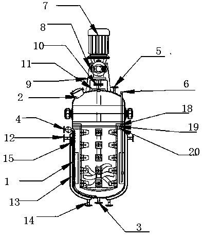
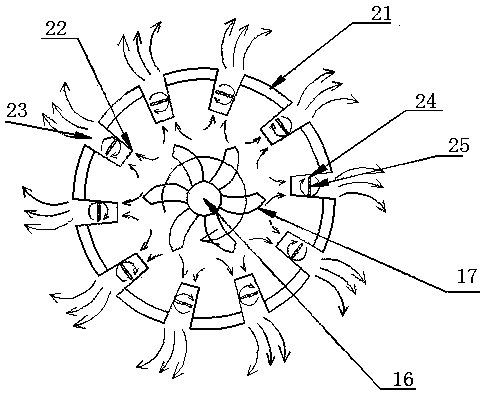
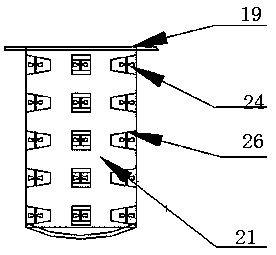
[0018] Embodiment 1: see Figure 1-Figure 3, a multi-fluid reaction device, the multi-fluid reaction device includes a tank assembly, a power assembly, a heat exchange assembly, a stirring assembly and a flow guide assembly; the power assembly is installed above the tank assembly; the stirring assembly It is installed inside the tank body assembly, and the top is connected with the power assembly; the guide assembly is installed in the tank body. The design structure is simple and clear, the components are closely connected and do not affect each other, the required parts are easy to replace, and it is easy to maintain the product during use in the future. The tank body components include tank body 1, manhole 2, outlet Liquid port 3, liquid inlet 4, pressure relief valve 5 and pressure outlet pipe 6; the manhole is installed on the left side of the top of the tank; the liquid inlet is located at the upper left side of the tank; the liquid outlet is located at the top of the ta...


PUM


Abstract

The invention relates to a multi-flow-state reaction device. The multi-flow-state reaction device is characterized by comprising a tank body assembly, a power assembly, a heat exchange assembly, a stirring assembly and a diversion assembly, wherein the power assembly is arranged above the tank body assembly; the stirring assembly is arranged inside the tank body assembly, and the top of the stirring assembly is connected with the power assembly; the diversion assembly comprises a cylinder body pressing plate, a cylinder body retaining block, a cylinder body support, a draft tube body, trapezoidal liquid inlets, trapezoidal liquid outlets, split paddles, sealing bearings and bearing fixing supports; the cylinder body support is fixed on the inner wall of a tank body; the cylinder body retaining block is fixed on the cylinder body support by the cylinder body pressing plate; the cylinder body retaining block is arranged at the top end of a draft tube of the cylinder body; the trapezoidalliquid inlets and the trapezoidal liquid outlets are both formed in the draft tube body; the sealing bearings are fixed on the cylinder wall in front of the trapezoidal liquid inlets by the bearing fixing supports; the split paddles are arranged on the corresponding sealing bearings.

Description

technical field [0001] The invention relates to a multi-fluid reaction device, which belongs to the technical field of chemical industry. Background technique [0002] The reaction device is an important processing tool in industrial production. Through the structural design and parameter configuration of the reactor container, the heating, evaporation, cooling and low-speed mixing functions required by the process can be realized. Reactors are widely used in petroleum, chemical, rubber, pesticides, dyes, medicine, food and other fields. They are mainly used as pressure vessels for vulcanization, nitration, hydrogenation, alkylation, polymerization, condensation and other processes. When the reaction kettle is stirring the liquid, if the rotation speed is too fast and the viscosity of the liquid to be stirred is low, it is easy to produce a columnar whirling zone in the kettle. The generation of the columnar convoluted area makes the liquid rotate rapidly following the agit...

Claims


Application Information

Patent Timeline
Patent Type & Authority Applications(China)
IPC IPC(8): B01J19/18
Inventor 卞春梅陈云锦
Owner 江苏和诺凯机械制造有限公司
Learn More