Electric Power Steering
A technology of electric power steering and motor, which is applied in the direction of electric steering mechanism, power steering mechanism, automatic steering control components, etc., and can solve problems such as out-of-control steering feeling, uncoordinated steering torque reduction, etc.
- Summary
- Abstract
- Description
- Claims
- Application Information
AI Technical Summary
Problems solved by technology
Method used
Image
Examples
no. 1 Embodiment approach 》
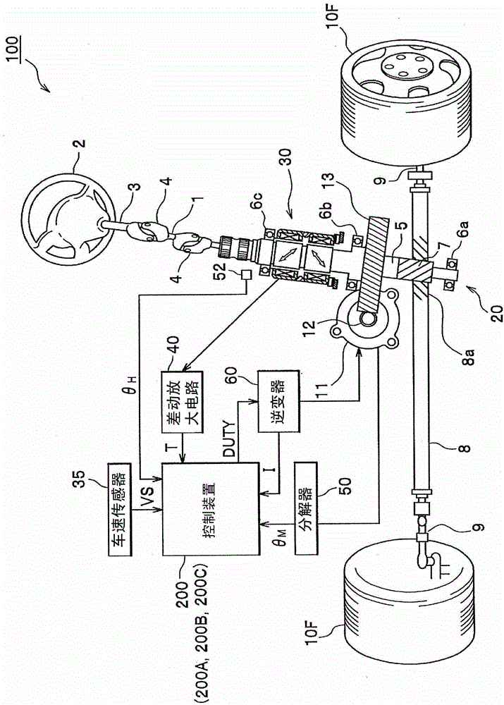
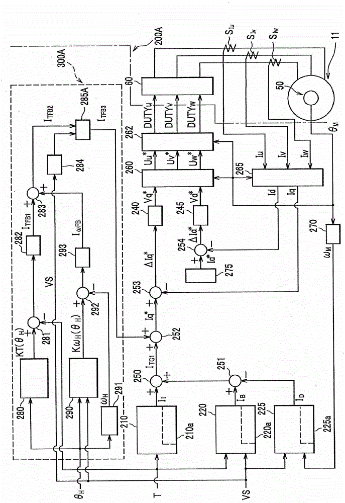
[0076] refer to figure 1 , figure 2 An electric power steering device according to an embodiment of the present invention will be described. figure 1 is a block diagram of an electric power steering device according to a first embodiment of the present invention, figure 2 It is a functional block configuration diagram of the control device of the first embodiment.
[0077] (Overall structure of electric power steering)
[0078] figure 1 In the electric power steering device 100 , a main steering rod 3 provided with a steering wheel (steering wheel) 2 , a shaft 1 , and a gear shaft 5 are connected by two universal joints 4 , 4 . In addition, a pinion gear 7 provided at the lower end of the pinion shaft 5 engages with rack teeth 8a of a rack shaft 8 capable of reciprocating movement in the vehicle width direction, and both ends of the rack shaft 8 are connected via Tie rods 9 and 9 connect unillustrated articulated arms of the left and right steering wheels 10F and 10F...
no. 2 Embodiment approach 》
[0202] Next, refer to Figure 8 , Figure 9 and refer appropriately to Figure 4 , Figure 12The control device (motor control unit) 200B in the electric power steering system 100 of the second embodiment will be described.
[0203] The control device 200B of the electric power steering apparatus 100 in the second embodiment differs from the control device 200A of the electric power steering apparatus 100 in the first embodiment in that the low vehicle speed steering reaction force control unit 300A is replaced with a low vehicle speed steering reaction force control unit 200A. Steering reaction force control unit 300B.
[0204] Components that are the same as in the first embodiment are denoted by the same reference numerals, and overlapping descriptions are omitted. Figure 8 It is a functional block diagram of the control device in the second embodiment, Figure 9 It is an explanatory diagram of the setting method of the steering angle responsive gain in the steering ang...
no. 3 Embodiment approach 》
[0243] In the first embodiment and the second embodiment, the target steering angular velocity calculation unit 290, the steering angular velocity calculation unit 291, the subtractor 292, the correction current conversion unit 293, and the adder 283 constitute the "fluctuation range" described in the technical scope. Suppression unit", but not limited thereto.
[0244] refer to Figure 10 Another configuration example of the fluctuation range suppressing means will be described.
[0245] Figure 10 It is a functional block configuration diagram of a low vehicle speed steering reaction force control unit in the control device in the third embodiment.
[0246] Figure 10 In the shown control device (motor control unit) 200C, the low vehicle speed steering reaction force control unit 300C will figure 2 The low vehicle speed steering reaction force control unit 300A of the control device 200A in the illustrated first embodiment or its modified example is changed to a low veh...
PUM
 Abstract
Description
Claims
Application Information
 - Generate Ideas
- Intellectual Property
- Life Sciences
- Materials
- Tech Scout
- Unparalleled Data Quality
- Higher Quality Content
- 60% Fewer Hallucinations
Browse by: Latest US Patents, China's latest patents, Technical Efficacy Thesaurus, Application Domain, Technology Topic, Popular Technical Reports.
© 2025 PatSnap. All rights reserved.Legal|Privacy policy|Modern Slavery Act Transparency Statement|Sitemap|About US| Contact US: help@patsnap.com


