a solenoid valve

A solenoid valve and electromagnet technology, applied in the field of solenoid valves, can solve problems such as the pollution of the inner cavity of the solenoid, the entry of high-pressure medium into the solenoid valve, etc., and achieve the effects of improving product life, improving life and reliability, and reducing weight

Active Publication Date: 2015-08-26
HENAN AEROSPACE HYDRAULIC & PNEUMATIC TECH
View PDF9 Cites 0 Cited by
  • Summary
  • Abstract
  • Description
  • Claims
  • Application Information

AI Technical Summary

Problems solved by technology

[0003] The purpose of the present invention is to provide a solenoid valve to solve the problem that the high-pressure medium of the existing solenoid valve enters the inner cavity of the electromagnet and causes the pollution of the inner cavity of the electromagnet

Method used


Image

  • a solenoid valve

Examples


Embodiment Construction

[0016] The present invention will be further described below in conjunction with the accompanying drawings and specific embodiments.

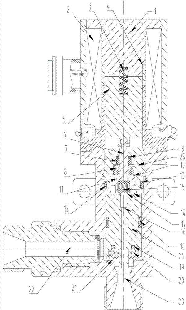
[0017] As shown in Fig. 1 is the structural diagram of the solenoid valve of the present invention, it can be seen from the figure that the solenoid valve is mainly composed of a valve body and an electromagnet assembly and a valve assembly arranged in the valve body. Among them, the electromagnet assembly includes a central sleeve 4 arranged vertically, a coil 2 arranged radially around the periphery of the central sleeve 4, an armature 5 axially slidably assembled in the central sleeve 4, and an armature installed in the central sleeve 4. The upper end is used to block and cooperate with the armature 5 when it goes up. At the junction of the armature 5 and the block 1, a blind hole is opened in the central axis of the respective end faces. The blind hole is provided with a press fit with the block 1. The spring 3.

[0018] The valve assembly...


PUM


Abstract

The invention discloses a solenoid valve. A sealing O-shaped ring for preventing gas from upwards extending is arranged between a secondary valve rod and a guide base, so that high-pressure gas is prevented from entering an inner cavity of an electromagnet, the inner cavity of the electromagnet is prevented from being polluted by working medium, and armature blocking caused by the fact that the residual medium enters the inner cavity of the electromagnet in the working process is prevented, so that abrasion is reduced, and the service life of the product is beneficially prolonged; meanwhile, a balancing cavity and a pressure storage cavity are formed on and under the secondary valve core, so that the electromagnet design burden is reduced greater by utilizing upper-lower gas pressure balancing factors of the secondary valve, and therefore, the weight of the product is lowered, the structure is more compact and the functions are more complete. Besides, the solenoid valve can be used for solving the problem that the sealing is invalid as the sealing force of the secondary valve is increased during a system pressure increasing process and the sealing surface of the secondary valve is damaged, and therefore, the structure of the solenoid valve can be used for prolonging the service life of the product and improving the reliability of the product.

Description

technical field [0001] The invention belongs to the field of valves, in particular to an electromagnetic valve. Background technique [0002] The public document with Chinese patent application number 201110263645.0 discloses a solenoid valve, including a main valve and a pilot valve. The main valve includes a valve seat, a piston accommodated in the valve seat and capable of axial movement. The input hole, output hole and pilot valve installation hole connected to the inner cavity; the pilot valve installation hole is located at the upper end of the inner cavity of the valve seat, and its center line is in the same direction as the piston movement direction, and the output hole is located at the bottom surface of the inner cavity of the valve seat and The lower end of the piston faces directly; the piston includes an upper end and a lower end, the diameter of the lower end is smaller than that of the upper end, the lower end is covered with the output hole, and the upper en...

Claims


Application Information

Patent Timeline
Patent Type & Authority Patents(China)
IPC IPC(8): F16K31/06F16K41/02F16K1/00F16K1/36F16K47/00
Inventor 侯云荆兵胡兆华刘宝林丁继洁刘刚孙爱民苏征
Owner HENAN AEROSPACE HYDRAULIC & PNEUMATIC TECH
Why Eureka
Try Eureka