
Dual-wavelength mould laser welding machine

A laser welding machine, laser welding technology, applied in laser welding equipment, lasers, welding equipment and other directions, can solve the problems of laser welding and processing, unable to form a stable molten pool, hinder the application of laser welding technology, etc., and achieve good welding effect. Effect

Inactive Publication Date: 2013-07-24
SHENZHEN TONGFA LASER EQUIP
View PDF4 Cites 6 Cited by
  • Summary
  • Abstract
  • Description
  • Claims
  • Application Information

AI Technical Summary

Problems solved by technology

Now industrially applied in the application of precision welding of metal materials, more than 90% of the common laser welding machines use 1064nm wavelength laser, 1064nm wavelength laser welding has low threshold, high conversion efficiency, good stability, mature technology, low cost, etc. Advantages, however, for some special metal materials such as copper, aluminum, etc., due to the high reflectivity of laser light with a wavelength of 1064nm, the maximum reflectivity of laser light with a wavelength of 1064nm can reach more than 95%, so when welding these metals, It is necessary to overcome most of the laser reflection energy, and when the welding point of this material is melted to form a molten pool, plasma will be formed on the welding point, and its laser reflectivity drops sharply to below 10%. At this time, the original used If the laser power is too high, it will not be able to form a stable molten pool, causing the solder joints to explode and the metal in the molten pool to splash
The welding difficulty caused by the huge contrast between the laser absorption rate in the initial stage of welding and welding has always plagued the laser welding and processing of high-reflective materials such as copper and aluminum.
It also greatly hinders the application of laser welding technology in the welding of these highly reflective materials

Method used


Image

  • Dual-wavelength mould laser welding machine

Examples


Embodiment Construction

[0009] The present invention will be described in further detail below in conjunction with the accompanying drawings.

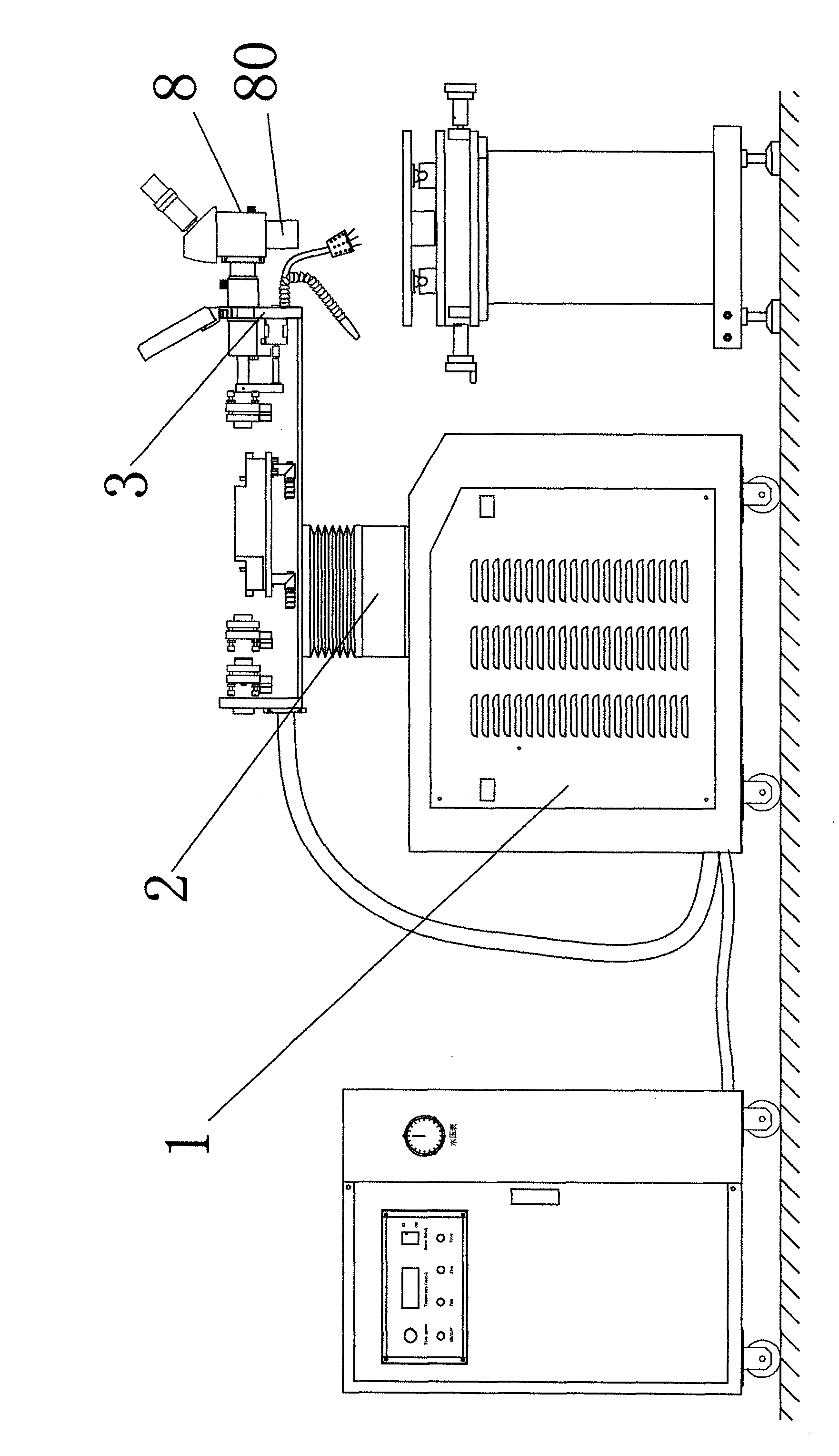
[0010] Please refer to figure 1 Shown is a preferred embodiment of the present invention. In this preferred embodiment, in order to achieve the above-mentioned purpose, the articulated optical fiber transmission mold laser welding machine of the present invention adopts the following technical scheme: comprising a main chassis 1, a laser generator 8, and a laser welding arm 2 arranged on the main frame , the main machine box 1 is provided with a main machine, the end of the laser welding arm 8 has a welding head 80 with a laser generator, the laser generator includes a laser resonator, and the dual-wavelength mold laser welding machine also includes a wavelength switching module group, the wavelength switching module includes a frequency doubling crystal insertion device 3 arranged at the laser resonator for inserting a frequency doubling crystal into the la...


PUM


Abstract

The invention relates to a dual-wavelength mould laser welding machine, which comprises a main machine box, a laser generator, a laser welding arm and a wavelength switching module, wherein the main machine box, the laser generator and the laser welding arm are arranged on a main machine frame, the interior of the main machine box is provided with a main machine, the tail end of the laser welding arm is provided with a welding head provided with the laser generator, the laser generator comprises a laser resonance cavity, the wavelength switching module comprises a frequency-doubling crystal inserting device, the frequency-doubling crystal inserting device is arranged in the laser resonance cavity and is used for inserting a frequency-doubling crystal into the laser resonance cavity, and the frequency-doubling crystal is a potassium titanium oxide phosphate crystal. The wavelength switching module can generate a 532NM laser, and the 532NM laser together with a 1064NM laser can be acted on the surface of the welded workpiece. Particularly for the high-reflecting material of which the original single wavelength laser is difficultly processed, the dual-wavelength common processing method is adopted, so the good welding effect is realized.

Description

technical field [0001] The field relates to a mold laser welding machine, in particular to a mold laser welding machine with a dual-wavelength working laser. Background technique [0002] Generally speaking, the shorter the wavelength of light, the better the absorption of the metal. For the green 532nm wavelength laser, for these 1064nm high-reflection materials, the absorption rate is very high, and a stable welding pool can be produced without a lot of power. . Now industrially applied in the application of precision welding of metal materials, more than 90% of the common laser welding machines use 1064nm wavelength laser, 1064nm wavelength laser welding has low threshold, high conversion efficiency, good stability, mature technology, low cost, etc. Advantages, however, for some special metal materials such as copper, aluminum, etc., due to the high reflectivity of laser light with a wavelength of 1064nm, the maximum reflectivity of laser light with a wavelength of 1064n...

Claims


Application Information

Patent Timeline
IPC IPC(8): B23K26/20H01S3/109B23K26/21
Inventor 王小峰
Owner SHENZHEN TONGFA LASER EQUIP
Learn More