
Micro-fluidic chip for inhibiting electroosmotic flows through grafting polyelectrolyte brush on surface of micro-channel

A polyelectrolyte brush and microfluidic chip technology, applied in the field of microfluidics, can solve the problems of demanding electric field strength, low precision, difficult operation, etc., and achieve the effects of high precision, improved control precision, and strong controllability

Inactive Publication Date: 2013-07-24
JILIN UNIV
View PDF2 Cites 0 Cited by
  • Summary
  • Abstract
  • Description
  • Claims
  • Application Information

AI Technical Summary

Problems solved by technology

[0005] The purpose of the present invention is to provide a microfluidic chip in which polyelectrolyte brushes are grafted on the surface of the microchannel to suppress electroosmotic flow, which solves the problems of difficult operation, low accuracy, and impact on electric field strength in the electroosmotic flow suppression method existing in the prior art. demanding issues

Method used


Image

  • Micro-fluidic chip for inhibiting electroosmotic flows through grafting polyelectrolyte brush on surface of micro-channel
  • Micro-fluidic chip for inhibiting electroosmotic flows through grafting polyelectrolyte brush on surface of micro-channel
  • Micro-fluidic chip for inhibiting electroosmotic flows through grafting polyelectrolyte brush on surface of micro-channel

Examples


Embodiment 1

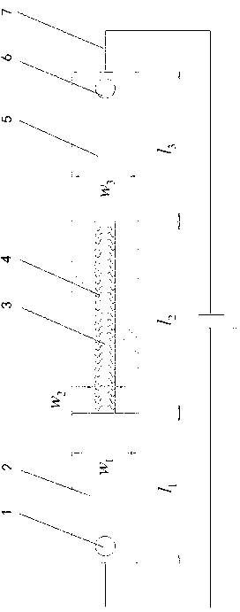
[0037] see figure 1 As shown, the present invention includes a sampling pool 1, an inlet channel 2, a slit channel 3, a polyelectrolyte brush 4, an outlet channel 5, a waste liquid pool 6, and a uniform electric field 7 parallel to the direction of the channel. Set the dimensions of each flow channel as follows: the length of the inlet flow channel 2 , the width of inlet runner 2 , the length of the slit runner 3 , the width of the slit runner 3 , the length of outlet channel 5 , the width of outlet channel 5 .

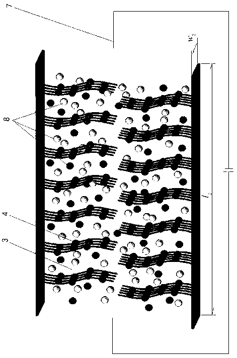
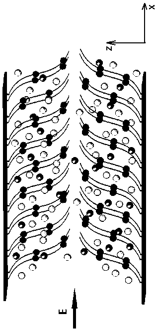
[0038] In the present invention, the surface of the slit channel 3 contains silicon crystal material. Hydroxyl-terminated polyvinyl alcohol (PVA) was prepared by active free radical method. The hydroxyl group at the terminal of the polyelectrolyte brush 4 reacts with the silanol group on the silicon wafer to form a polyelectrolyte brush. grafting density , Represents no polyelectrolyte brushing effect. And apply a uniform electric field 7 in the dir...


PUM


Abstract

The invention relates to a micro-fluidic chip for inhibiting electroosmotic flows through grafting a polyelectrolyte brush on the surface of a micro-channel, belonging to the field of microfluidics. The micro-fluidic chip comprises a sample feeding pool, an inlet channel, a slit channel, an outlet channel and a waste liquid pool which are sequentially communicated, wherein a polyelectrolyte brush with cations is grafted on the channel surface of the inside of the slit channel, and an uniform electric field is applied parallel to the direction of the channel so as to drive fluid to flow. Under the action of the uniform electric field, the polyelectrolyte brush grafted on the surface of the micro-channel extends along the direction of the electric field, and the fluid in the micro-channel is under the action of the viscous friction and electrostatic attraction of the polyelectrolyte brush, so that surface charges in the channel are balanced, reduced or inhibited; and due to the attraction action among solvent particles and the polyelectrolyte brush, the solvent particles are impregnated into a polyelectrolyte brush layer, thereby achieving the purpose of inhibiting electroosmotic flows. The micro-fluidic chip disclosed by the invention can improve the separation precision of proteins and DNA (deoxyribonucleic acid) molecules, and has the advantages of wide applicability, strong controllability and the like.

Description

technical field [0001] The invention relates to the field of microfluidics, in particular to a microfluidic chip capable of effectively suppressing electroosmotic flow in a microfluidic channel, especially a microfluidic chip grafted with polyelectrolyte brushes on the surface of a microfluidic channel to suppress electroosmotic flow. It can balance, reduce or suppress the negative charge on the surface of the micro-channel material, thereby inhibiting the electroosmotic flow in the micro-channel, and can be applied to protein analysis and separation, DNA separation and other fields. Background technique [0002] Electroosmotic flow is a fluid flow caused by the negative charge on the surface of the microchannel material, and when an electric field is applied to the fluid, the electrostatic charge is driven by Coulomb force. In microfluidic chips, suppression of electroosmotic flow improves separation efficiency, reproducibility, and resolution. In applications such as ...

Claims


Application Information

Patent Timeline
IPC IPC(8): B01L3/00
Inventor 左雨欣王国强于影左春柽王祎睿胡冬枚
Owner JILIN UNIV
Learn More