A MMC Circulation Suppression Technology Based on Second Harmonic Trap

A second harmonic and circulating current suppression technology, applied in the direction of output power conversion devices, electrical components, etc.

Inactive Publication Date: 2016-01-13
SOUTHEAST UNIV
View PDF5 Cites 0 Cited by
  • Summary
  • Abstract
  • Description
  • Claims
  • Application Information

AI Technical Summary

Problems solved by technology

However, the current research r

Method used


Image

  • A MMC Circulation Suppression Technology Based on Second Harmonic Trap
  • A MMC Circulation Suppression Technology Based on Second Harmonic Trap
  • A MMC Circulation Suppression Technology Based on Second Harmonic Trap

Examples


Embodiment Construction

[0022] specific implementation plan

[0023] The technical solution of the present invention will be further described in detail below in conjunction with the accompanying drawings.

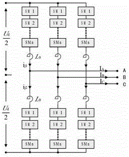
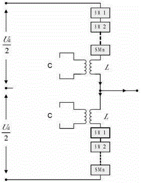
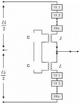
[0024] ) used in the present invention Option One The structure of the MMC circuit after the introduced circulation suppression method is as follows figure 2 shown. and figure 1 Compared with the original MMC circuit shown, it can be found that the modification of the circuit topology of this scheme is mainly to replace the original current-limiting inductance L0 on the bridge arm of the traditional MMC converter circuit with image 3 Circuit E shown. Since the main component of the circulating current is the second harmonic component, by adjusting the LC circuit on the secondary side of the coupled inductor to make it resonate in parallel when the second harmonic flows through, the second harmonic trap circuit can be formed, thus effectively ground to suppress the second harmonic flowing...


PUM


Abstract

The invention discloses an MMC bridge arm circulation suppression circuit based on a second harmonic trap. The invention aims at the fact that the main component in the circulating current of the MMC bridge arm is the second harmonic, and uses a coupled inductor to replace the original bridge arm current-limiting inductor, and builds an LC resonant circuit on the secondary side of the coupled inductor to make it resonate The frequency is twice the frequency of the fundamental wave, so that the fundamental wave current in the bridge arm current can flow normally, but the secondary current is suppressed, thereby effectively suppressing the circulating current on the bridge arm.

Description

technical field [0001] The present invention designs a method for suppressing circulating current of a modular multilevel converter. The method is based on an inductive coupling circuit and an LC resonant circuit. By adjusting parameters, the resonant frequency of the circuit is twice the frequency of the fundamental wave, thereby forming a second harmonic A wave trap circuit belongs to the field of application of power electronics in power systems. Background technique [0002] Modular multilevel converter (MMC) is a new type of multilevel voltage conversion circuit, which can superimpose and output very high voltage by cascading multiple sub-modules. Compared with the traditional multi-level topology, the modified topology has the characteristics of less output harmonics and high modularity, so it has broad application prospects in power systems. [0003] Compared with previous multilevel converters, MMC has many advantages, but it also brings some new problems. One of t...

Claims


Application Information

Patent Timeline
IPC IPC(8): H02M1/12
Inventor 梅军郑建勇杜晓舟吉宇韩少华
Owner SOUTHEAST UNIV
Why Eureka
Try Eureka