
Single-cavity double-electrode discharge cavity with micro-channel structure

A discharge cavity and double-electrode technology, which is applied in the field of lasers, can solve the problems of complex manufacturing process and operation method, complex system structure, and high laser price, and achieve the effects of reducing bit arc phenomenon, increasing laser energy, and reducing complexity

Inactive Publication Date: 2013-07-10
ACAD OF OPTO ELECTRONICS CHINESE ACAD OF SCI
View PDF9 Cites 2 Cited by
  • Summary
  • Abstract
  • Description
  • Claims
  • Application Information

AI Technical Summary

Problems solved by technology

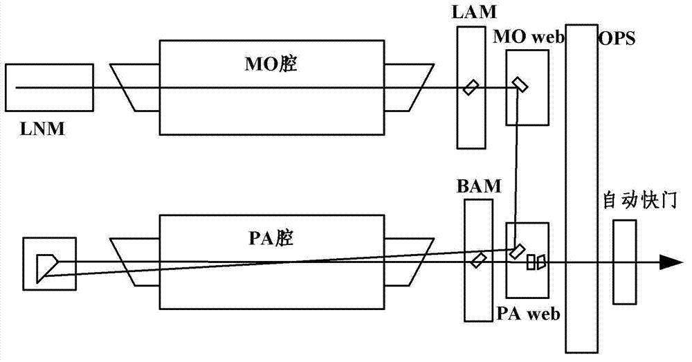
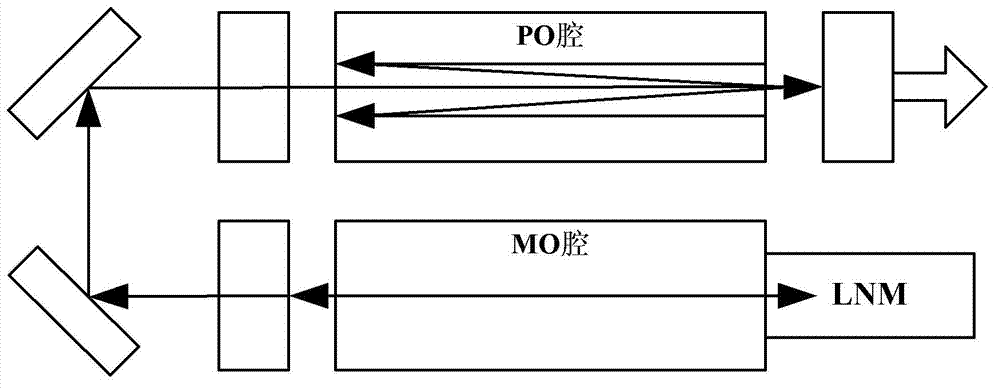
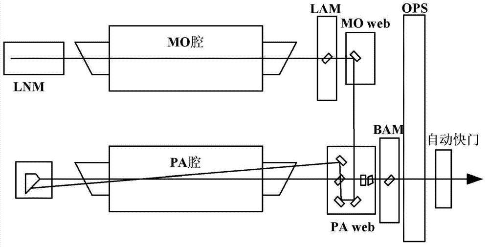
[0021] Aiming at the disadvantages of MOPA, MOPRA, and MOPO system structures used in existing dual-cavity excimer lasers, the technical problem to be solved by the present invention is to propose a new type of single-cavity double-electrode discharge cavity and corresponding lasers to solve the problem based on dual-cavity The structural laser has the disadvantages of high price, large volume, complicated manufacturing process and operation method, and can achieve narrow linewidth and high-power high-quality laser beam output

Method used


Image

  • Single-cavity double-electrode discharge cavity with micro-channel structure
  • Single-cavity double-electrode discharge cavity with micro-channel structure
  • Single-cavity double-electrode discharge cavity with micro-channel structure

Examples


Embodiment Construction

[0053] In order to make the object, technical solution and advantages of the present invention clearer, the present invention will be described in further detail below in conjunction with specific embodiments and with reference to the accompanying drawings.

[0054] 1. Basic structure of a single-chamber double-electrode discharge chamber

[0055] Figure 6 It is a structural diagram of a single-chamber double-electrode discharge chamber according to an embodiment of the present invention. Such as Figure 6 As shown, the discharge chamber mainly includes a discharge chamber body 1 , two sets of main discharge electrodes, two sets of gas circulation systems, a heat dissipation system, a dust removal device and a high-voltage pulse charging module 4 .

[0056] The discharge chamber body 1 is a closed gas container, which is designed to implement the relevant standards of pressure vessels, and is used to store 3-6 atm corrosive mixed gases, such as including F 2 Excimer haloge...


PUM

PropertyMeasurementUnit
Widthaaaaaaaaaa
Depthaaaaaaaaaa

Abstract

The invention relates to a single-cavity double-electrode discharge cavity with a micro-channel structure. The single-cavity double-electrode discharge cavity with the micro-channel structure comprises a cavity body, a fan and two sets of main discharge electrodes. The cavity comprises a left chamber and a right chamber which form a symmetrical double-chamber structural cavity shape. The shape of the section of each chamber is in a pear shape which is small on the upper portion and big on the lower portion. The left chamber and the right chamber intersect at a symmetrical surface of the whole discharge cavity and are communicated with each other. The two sets of main discharge electrodes are respectively located on the upper side of the left chamber and on the upper side of the right chamber. The fan drives gas in the discharge cavity to pass through the discharge electrodes and flow to form main airflow. Micro-channels are arranged on two sides of a channel of the main airflow. The single-cavity double-electrode discharge cavity achieves a double-cavity function of a master oscillator power amplifier (MOPA) structure, a master oscillator power oscillator (MOPO) structure and a master oscillator power regenerative amplifier (MOPRA) structure through a sing-cavity structure, reduces complexity of a system, and ensures discharge synchronism. In addition, the micro-channel structure can prevent eddy airflow from generating, reduces arcing phenomena generated on the side faces of the discharge electrodes, increases discharge stability, improves laser energy, and prolongs the service life of preionization electrodes.

Description

technical field [0001] The invention belongs to the technical field of lasers, and in particular relates to a single-cavity double-electrode discharge cavity of an excimer laser and an excimer laser including the discharge cavity, in particular to a single-cavity double-electrode discharge cavity with a microchannel structure. The discharge chamber of the present invention can also be applied to other devices in which gas is excited to generate energy radiation. Background technique [0002] Excimer laser is a conventional gas laser for ultraviolet characteristic applications. It is currently considered to be the best light source choice for lithography, and it is the main working light source in the integrated circuit lithography lithography industry. [0003] Traditional discharge excited excimer lasers are designed with a single-cavity single-electrode structure. With the further development of optical lithography technology, the light source is required to have narrower...

Claims


Application Information

Patent Timeline
IPC IPC(8): H01S3/03H01S3/036
Inventor 丁金滨刘斌王宇周翊赵江山
Owner ACAD OF OPTO ELECTRONICS CHINESE ACAD OF SCI
Learn More