Electrode lead-out structure

An electrode extraction and cell technology, applied in structural parts, hybrid capacitor electrodes, circuits, etc., can solve problems such as affecting the production efficiency of energy storage devices, sudden changes in performance of energy storage devices, and increasing processing difficulty, saving assembly time and extending Service life, the effect of increasing the conductive contact area

Active Publication Date: 2016-04-20
ZHENGZHOU SINO CRYSTAL DIAMOND
View PDF5 Cites 2 Cited by
  • Summary
  • Abstract
  • Description
  • Claims
  • Application Information

AI Technical Summary

Problems solved by technology

[0003] At present, commonly used electrode lead-out structures such as figure 1 As shown, it includes a current collecting plate 02 that is in electrical contact with the internal cells of the battery or supercapacitor and an end cap 03 that is buckled on the current collecting plate 02, and a columnar shape is protruded on one side of the current collecting plate 02 The connection protrusion 02-1 is correspondingly provided with a blind connection hole 03-1 on the end surface of the end cover 03 for interference fit with the connection protrusion 02-1, and on the other end surface of the end cover 03 is provided with a Lead out the pole 03-2, and the end cover 03 is conductively fixedly connected by connecting the blind hole 03-1 with the connection protrusion 02-1 of the current collector 02, and connects the battery or supercapacitor through the lead out pole 03-2. The electric power is drawn out, so as to realize the fixed connection between the end cover 03 and the collector plate 02. Although this electrode lead-out structure is reliable in connection and compact in structure, it can generally only use the principle of thermal expansion and contraction of metals, through thermal packing or cold Assemble
During use, if encountering high temperature or low temperature, the connection between the end cap and the collector plate may be loosened, resulting in a sudden change in the performance of the energy storage device, or even failure, so that there are many uncertainties in the performance of the energy storage device; secondly, this This kind of electrode lead-out structure adopts interference fit, which requires precise control of the accuracy of the connection part, which increases the difficulty of processing; in addition, before assembly, the end cover and current collector plate need to be pretreated by cooling or heating, which affects the energy storage device. production efficiency, increased assembly costs

Method used


Image

  • Electrode lead-out structure
  • Electrode lead-out structure
  • Electrode lead-out structure

Examples


Embodiment 3

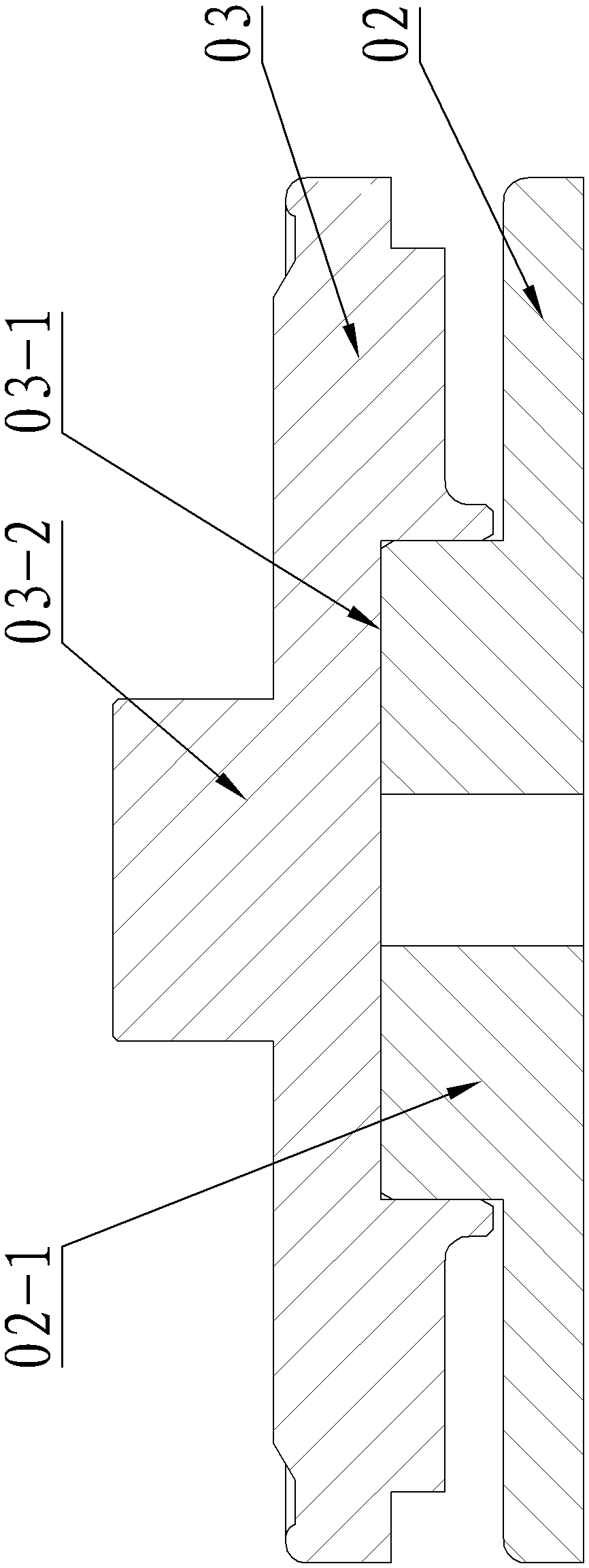
[0032] Embodiment 3 of the electrode lead-out structure of the present invention: as Figure 5 As shown, the difference between this embodiment and Embodiment 1 is that the upper collector plate 32 is composed of a plate body 32-1 and a collector plate protrusion 32-2 protruding from the upper edge of the plate body 32-1. 32-2 is a sleeve shape, the inner peripheral surface of the collector plate protrusion 32-2 and the part of the plate body 32-1 in the collector plate protrusion form a blind hole-like positioning hole, and the end cover 31 is formed by the end cover The disc body 31-1 and the end cap protrusion 31-4 protruding from the lower end surface of the end cap disc body 31-1 are formed, the end cap protrusion 31-4 is solid columnar, and the end cap protrusion 31-4 is transitionally inserted in The upper end of the positioning hole has a retaining edge surrounding the end cap protrusion 31-4 on the lower end surface of the end cap disc body 31-1, and the retaining edg...


PUM


Abstract

The invention discloses an electrode lead-out structure. According to the electrode lead-out structure, a positioning projection and a positioning hole are arranged on the opposite end faces of an end cover and a current collecting plate respectively; the positioning projection is inserted into the positioning hole in a transitional mode; a combining part is arranged at the periphery of the positioning projection and the positioning hole and in the combining position of the end faces of the end cover and the current collecting plate; and a welding structure fixedly connected with the end cover and the current collecting plate is arranged on the combining part. By virtue of transitional insertion and welding modes, the positioning projection is inserted into the positioning hole by pressing or knocking, and the end cover and the current collecting plate do not need to be subjected to pretreatment of cooling or heating, so that the assembling time is saved, the production efficiency is improved, and the cost is reduced.

Description

technical field [0001] The invention relates to the technical field of electrode lead-out structures, in particular to an electrode lead-out structure of a battery or a supercapacitor. Background technique [0002] Batteries or supercapacitors are widely used as energy storage devices in industry, energy, military and other fields. Its electrode lead-out structure mainly plays the role of connecting the inner core body and the outer end cap. As a key link in production, the electrode lead-out structure used not only has an important impact on the resistance of the energy storage device, but is also crucial to the stability, reliability and life of the monomer. [0003] At present, commonly used electrode lead-out structures such as figure 1 As shown, it includes a current collecting plate 02 that is in electrical contact with the internal cells of the battery or supercapacitor and an end cap 03 that is buckled on the current collecting plate 02, and a columnar shape is pro...

Claims


Application Information

Patent Timeline
Patent Type & Authority Patents(China)
IPC IPC(8): H01M2/20H01M2/26H01G11/28H01G11/74
CPCY02E60/10
Inventor 徐梅赵志伟宋旭升王鹏张红涛杜军
Owner ZHENGZHOU SINO CRYSTAL DIAMOND
Why Eureka
Try Eureka