
a gasifier

A technology of gasification furnace and furnace body, which is applied in the field of gasification furnace, and can solve the problems of less gas, insufficient gas concentration, falling and compacting of fuel, etc.

Inactive Publication Date: 2014-10-15
周福忠
View PDF8 Cites 0 Cited by
  • Summary
  • Abstract
  • Description
  • Claims
  • Application Information

AI Technical Summary

Problems solved by technology

[0002] With the continuous development of society and the continuous improvement of the level of science and technology, more and more people pay more and more attention to the rational use of energy. As an energy recycling device, the gasifier has been widely used. Among related products, gasification When the furnace is in use, it often occurs that the bottom of the fuel cannot be dropped and compacted after the bottom of the fuel is burnt out during oxygen-deficient combustion, resulting in less gas produced, and thus insufficient concentration of gas entering the gas pipe, which makes the stove head of the gasifier There is a phenomenon of flameout

Method used


Image

  • a gasifier
  • a gasifier

Examples


Embodiment 1

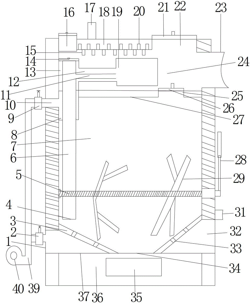
[0013] Example 1, such as figure 1 Shown, a kind of gasification furnace comprises furnace body 1, is provided with pressing shaft 4 in furnace body 1, is provided with pressing claw 29 on the pressing shaft 4, and one end of pressing shaft 4 passes through furnace body 1 and is connected with The furnace body 1 is rotatably connected, and one end of the pressing shaft 4 passing through the furnace body 1 is connected with a pressing handle 28 .

[0014] In the gasification furnace of the above embodiment, after the fuel in the furnace body 1 is burned out, the flame becomes weaker, and the pressing handle 28 is pressed back and forth to drive the pressing shaft 4, and the pressing claw 29 on the pressing shaft 4 is stirred The fuel drives the fuel to fall, and the fuel at the bottom is compacted, which can continuously generate gas and avoid the occurrence of flameout.

Embodiment 2

[0015] Example 2, such as figure 1 and figure 2 Shown, a kind of gasification furnace comprises furnace body 1, is provided with pressing shaft 4 in furnace body 1, is provided with pressing claw 29 on the pressing shaft 4, and one end of pressing shaft 4 passes through furnace body 1 and is connected with The furnace body 1 is rotatably connected, and one end of the pressing shaft 4 passing through the furnace body 1 is connected with a pressing handle 28 .

[0016] The body of heater 1 is divided into an upper combustion chamber 24 and a lower combustion chamber 7 by a partition 27, the binder shaft 4 is positioned in the lower combustion chamber 7, and one side of the upper combustion chamber 24 top is provided with a stove mouth 22, and the stove mouth 22 is provided with a A stove mouth cover 21 is arranged, and the dividing plate 27 is provided with a feed port 25, and the feed port 25 is provided with a feed port cover 26. One side of the top of the upper combustion ...


PUM


Abstract

The invention relates to the field of gas appliances, and particularly relates to a gasification furnace. The gasification furnace comprises a furnace body, wherein the furnace body is internally provided with a material pressing shaft, the material pressing shaft is provided with a material pressing claw, one end f the material pressing shaft penetrates through the furnace body, and is connected with the furnace body in a rotatable body, and one end, penetrating through the furnace body, of the material pressing shaft is connected with a material pressing handle. According to the gasification furnace provided by the invention, flames become weak after fuel in the furnace body is burnt out, the material pressing handle is repeatedly pressed to drive the material pressing shaft, the fuel is stirred by the material pressing claw on the material pressing shaft, the fuel is driven to fall down, and the fuel at the bottom is tightly compacted, so that gas can be continuously generated, and the flameout phenomenon can be prevented.

Description

technical field [0001] The invention relates to the field of burning appliances, in particular to a gasifier. Background technique [0002] With the continuous development of society and the continuous improvement of the level of science and technology, more and more people pay more and more attention to the rational use of energy. As an energy reuse device, the gasifier has been widely used. Among related products, gasification When the furnace is in use, it often occurs that the bottom of the fuel cannot be dropped and compacted after the bottom of the fuel is burnt out during oxygen-deficient combustion, resulting in less gas being produced, and thus the concentration of gas entering the gas pipe is insufficient, making the burner of the gasifier There is a phenomenon of flameout. Contents of the invention [0003] The object of the present invention is to provide a gasifier to solve the above problems. [0004] In an embodiment of the present invention, a gasificatio...

Claims


Application Information

Patent Timeline
Patent Type & Authority Patents(China)
IPC IPC(8): C10J3/20C10J3/32C10J3/72C10J3/76F24B1/18F24B1/183
Inventor 周福忠张纯东
Owner 周福忠
Learn More