Stone removing crusher

A technology of crusher and gravel, applied in grain processing and other directions, can solve the problems of easily damaged gravel rollers, high difficulty in replacement and assembly, and increased production costs.

Inactive Publication Date: 2013-07-10
山东矿机迈科建材机械有限公司
View PDF12 Cites 1 Cited by
  • Summary
  • Abstract
  • Description
  • Claims
  • Application Information

AI Technical Summary

Problems solved by technology

Existing pulverizers mainly include hammer crusher and double-roll crusher. Hammer crusher has disadvantages such as complex structure and low crushing efficiency; currently used double-roll crusher includes a frame and two parallel rollers arranged on the frame. The frame is equipped with a power device that drives the two support shafts to rotate in opposite directions. The two support shafts are equipped with oppositely arranged gravel rollers. When the power device operates, the two support shafts are driven to rotate in opposite directions. Raw materials are put into the top of the rollers, and the two gravel rollers squeeze against each other to crush the raw materials. The double-roller crusher with the above structure is difficult to replace and assemble. It is extremely easy to damage the surface of the crushing roller. When damaged, the entire roller needs to be replaced, thus increasing the production cost. Using a crusher with a damaged surface of the crushing roller is likely to cause poor crushing effect

Method used


Image

  • Stone removing crusher
  • Stone removing crusher
  • Stone removing crusher

Examples


Embodiment Construction

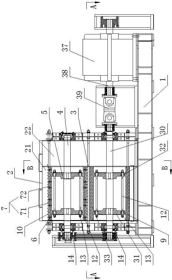
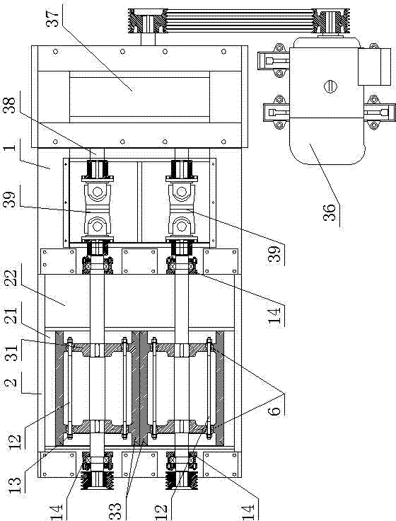
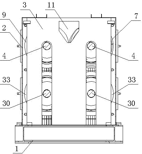
[0022] Such as figure 1 The stone removal crusher shown includes a frame 1, on which a stone removal and gravel bin 2 with a feed inlet is installed on the frame 1, and the stone removal and gravel bin 2 is surrounded by oppositely arranged side plates and passed through Fastened by the bolts, the stone removal bin 2 is equipped with a partition plate 3 that divides its inner cavity into a crushing chamber 21 and a tailing chamber 22. The bottoms of the crushing chamber 21 and the tailing chamber 22 are respectively provided with outlet The feed opening, the partition plate 3 is provided with a feed opening 11 connecting the upper part of the crushing chamber 21 and the tailing chamber 22, and the crushing chamber 21 is provided with a rotating connection on the wall of the stone removal chamber 2 and driven by a power device. For the two crushing shafts 4 rotating in opposite directions, the frame 1 is also equipped with a secondary crushing shaft 30 that is located below the...


PUM


Abstract

The invention discloses a stone removing crusher comprising a rack, wherein a stone removing and crushing bin with a feeding hole at the top is arranged on the rack, a spacing board is arranged in the stone removing and crushing bin, discharge holes are formed at the bottoms of a stone crushing cavity and a tailing cavity respectively, a material passing-through hole is formed in the spacing board, two stone crushing shafts are arranged in the stone crushing cavity, two support disks are arranged on the two stone crushing shafts respectively and correspondingly, radial expansion rings are sheathed at the outer side of each support disk, a stone crushing roller is also sheathed at the outer sides of the two radial expansion rings on one support disk, a smooth stone crushing roller is sheathed at the outer sides of the two radial expansion rings on the other support disk, the material passing-through hole is formed at one side of a space between the stone crushing roller and the smooth stone crushing roller, the contact surfaces of the two radial expansion rings and the support disks or the stone crushing roller and the smooth stone crushing roller are fitted in a conical surface manner, and an expansion power device used for driving the two radial expansion rings to move oppositely is arranged in the stone removing and crushing bin. The stone removing crusher has the beneficial effects of quickness and convenience in assembly and replacement, low production cost and good stone crushing and removing effects.

Description

technical field [0001] The invention relates to a stone removing crusher. Background technique [0002] In existing brick factories and manufacturers of silt ceramsite, it is necessary to use crushers to finely pulverize raw materials. Existing pulverizers mainly include hammer crusher and double-roll crusher. Hammer crusher has disadvantages such as complex structure and low crushing efficiency; currently used double-roll crusher includes a frame and two parallel rollers arranged on the frame. The frame is equipped with a power device that drives the two support shafts to rotate in opposite directions. The two support shafts are equipped with oppositely arranged gravel rollers. When the power device operates, the two support shafts are driven to rotate in opposite directions. Raw materials are put into the top of the rollers, and the two gravel rollers squeeze against each other to crush the raw materials. The double-roller crusher with the above structure is difficult to ...

Claims


Application Information

Patent Timeline
IPC IPC(8): B02C4/08B02C4/28B02C4/32B02C4/30
Inventor 赵笃学刘浩田清峰
Owner 山东矿机迈科建材机械有限公司
Why Eureka
Try Eureka