Power circuit for light emitting diode (LED) illuminating lamp

A technology of LED lighting and power circuits, which is applied in the layout of electric lamp circuits, electric light sources, lighting devices, etc. It can solve problems such as accelerated light decay, shortened LED service life, and hot lamp beads, so as to reduce heat generation and prevent fatigue Phenomenon, the effect of prolonging the service life

Inactive Publication Date: 2013-07-03
胡益锋
View PDF16 Cites 3 Cited by
  • Summary
  • Abstract
  • Description
  • Claims
  • Application Information

AI Technical Summary

Problems solved by technology

The luminous efficiency and service life of LED lighting lamps have a great relationship with their power supply circuits. The existing LED lighting lamps all adopt a stable DC power supply circuit, and try to stabilize the voltage and current as much as possible. Looking at the more famous LED companies now, including Beijing Famous LED lighting companies such as Opples, Shanghai Baolip, Zhejiang Chint, Wenzhou Focus, Shenzhen Grimmy, and the world brand Philips are all using LED lamps driven by traditional DC circuits. The outdoor high-power LED street lights represented by Philips all use switching power supply as the drive circuit, while for low-power LED lights (not exceeding 15W), they are bulb-type and fluorescent lamp-type household LED lights represented by Philips. The capacitive current-limiting full-bridge rectifier DC power supply circuit, although the luminous intensity of the LED lamp designed in this way is very high, but the most fatal shortcoming is that it will make the lamp bead hot, and as long as the LED lamp bead is hot, the light decay will be greatly reduced. Speed ​​up, so it will obviously shorten the service life of LED, which is much shorter than the nominal service life (50,000 hours)

Method used


Image

  • Power circuit for light emitting diode (LED) illuminating lamp
  • Power circuit for light emitting diode (LED) illuminating lamp
  • Power circuit for light emitting diode (LED) illuminating lamp

Examples


Embodiment Construction

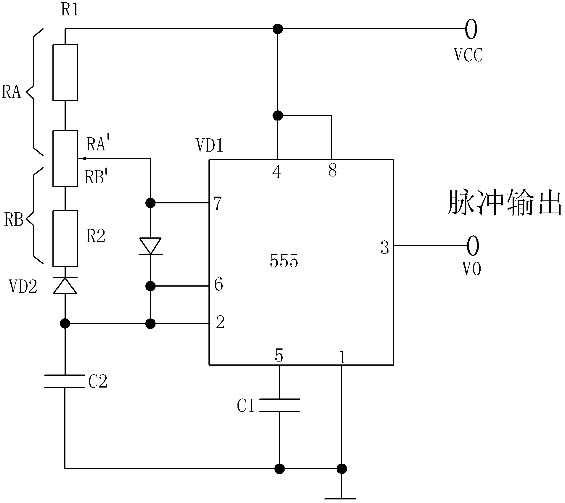
[0011] The LED lighting power supply circuit of the utility model is a conversion circuit for converting mains electricity into DC pulsating voltage. The pulsating frequency is between 100 and 200 Hz. If the pulsating frequency is too low, flickering will occur. If the pulsating frequency is too high, the cooling effect will be reduced. Not noticeable, 100 to 120 Hz is the best. The circuit can have various forms. For low-power LED lighting (not exceeding 15W), a full-bridge rectifier DC pulsating power supply circuit with a current-limiting capacitor connected in series on the AC side can be used, such as figure 1 As shown, the difference from the traditional full-bridge rectifier circuit is that there is no filter capacitor on the DC output side, and the direct output of the DC pulsating voltage is the power supply of the low-power LED lighting. The capacity of the current-limiting capacitor is determined according to the specific power of the LED lighting. I won't repeat th...


PUM


Abstract

The invention relates to a power circuit for a light emitting diode (LED) illuminating lamp. The power circuit is a conversion circuit converting mains supply into direct current ripple voltage with ripple frequency between 100Hz and 200Hz. As the power circuit for the LED lamp can convert the mains supply into the direct current ripple voltage, the LED is switched on to emit light only in a pulse high level receiving time interval but stops emitting light in a pulse low level receiving time interval, and therefore, the LED is in an on/off alternate state, fatigue, caused by long-time continuous working, of the LED, can be avoided, heat productivity is reduced, service life of the LED is prolonged greatly, and consumption of nonferrous materials for a radiator is reduced.

Description

technical field [0001] The invention relates to a power supply circuit, in particular to a power supply circuit of an LED lighting lamp. Background technique [0002] With the deepening of people's understanding of the concept of energy saving and environmental protection, and the encouragement of national policies, the application of LED light sources is constantly being promoted. LED lamps are mainly divided into higher-power flat-panel street lamps (above 30W) for outdoor use, LED fluorescent lamps and low-power LED bulbs (less than 15W) for household use. The luminous efficiency and service life of LED lighting lamps have a great relationship with their power supply circuits. The existing LED lighting lamps all adopt a stable DC power supply circuit, and try to stabilize the voltage and current as much as possible. Looking at the more famous LED companies now, including Beijing Famous LED lighting companies such as Opples, Shanghai Baolip, Zhejiang Chint, Wenzhou Focus...

Claims


Application Information

Patent Timeline
Patent Type & Authority Applications(China)
IPC IPC(8): H05B37/00H05B37/02
Inventor 胡益锋
Owner 胡益锋
Why Eureka
Try Eureka