Eureka AIR delivers breakthrough ideas for toughest innovation challenges, trusted by R&D personnel around the world.

Automatic Control System For Mechanical Ventilation For Active Or Passive Subjects

a control system and passive subject technology, applied in the field of mechanical ventilators, can solve the problems of increasing the mortality and morbidity rate of patients on mechanical ventilation, increasing the work rate of breathing, and causing asynchrony between the machine and the patient, so as to prevent fatigue and dyspnea, reduce the work rate of breathing, and increase the support level

Active Publication Date: 2011-01-27
TEHRANI FLEUR T
View PDF8 Cites 39 Cited by
  • Summary
  • Abstract
  • Description
  • Claims
  • Application Information

AI Technical Summary

Benefits of technology

[0010]The present invention realizes many advantages over the prior art. While it achieves a desired synchronization between the patient and the ventilator, it guarantees that the patient receives a minimum required ventilation regardless of the strength of the patient's spontaneous breathing effort, both passive and active patients can be treated by the system, and it may be used in the management as well as the weaning phase of ventilatory treatment.

Problems solved by technology

Provision of inappropriate treatment can cause numerous untoward conditions in patients and induce asynchrony between the machine and the patient.
Lack of synchrony between the patient and the ventilator can significantly increase work of breathing, necessitate administration of sedatives, prolong the treatment and delay weaning which can all cause complications that may lead to increased mortality and morbidity rates of patients on mechanical ventilation.
In this technique, the ventilator followed the patient's spontaneous respiratory pattern, and therefore, there was significant synchrony between the machine and the patient.
A major drawback of this system, known as proportional assist ventilation, is that it cannot guarantee the delivery of a minimum amount of ventilation to the patient.
This may lead to a hazardous situation if the patient's spontaneous breathing activity weakens with time or if the patient develops dyspnea due to fatigue or other causes.

Method used


Image

  • Automatic Control System For Mechanical Ventilation For Active Or Passive Subjects
  • Automatic Control System For Mechanical Ventilation For Active Or Passive Subjects
  • Automatic Control System For Mechanical Ventilation For Active Or Passive Subjects

Examples


example

[0043]During ventilatory treatment, the average measured minute ventilation, AMMV, is calculated to be 5 lit / min, the required minute ventilation, RMV, is calculated to be 7 lit / min, and the support level, α, is 0.5. Using equation 18, the new support level is calculated as:

α1=1+(AMMV / RMV)(α−1)=1+(5 / 7)(0.5−1)=0.64

[0044]If more push is required in the weaning phase, and the weaning factor β is 0.8, then the new support level is calculated by using equation 19 as:

α1=1+(AMMV / RMV)(α−1)(1 / β)=1+(5 / 7)(0.5−1)(1 / 0.8)=0.55

[0045]Therefore, the new support level can be adjusted accordingly.

Description of the Preferred Embodiments

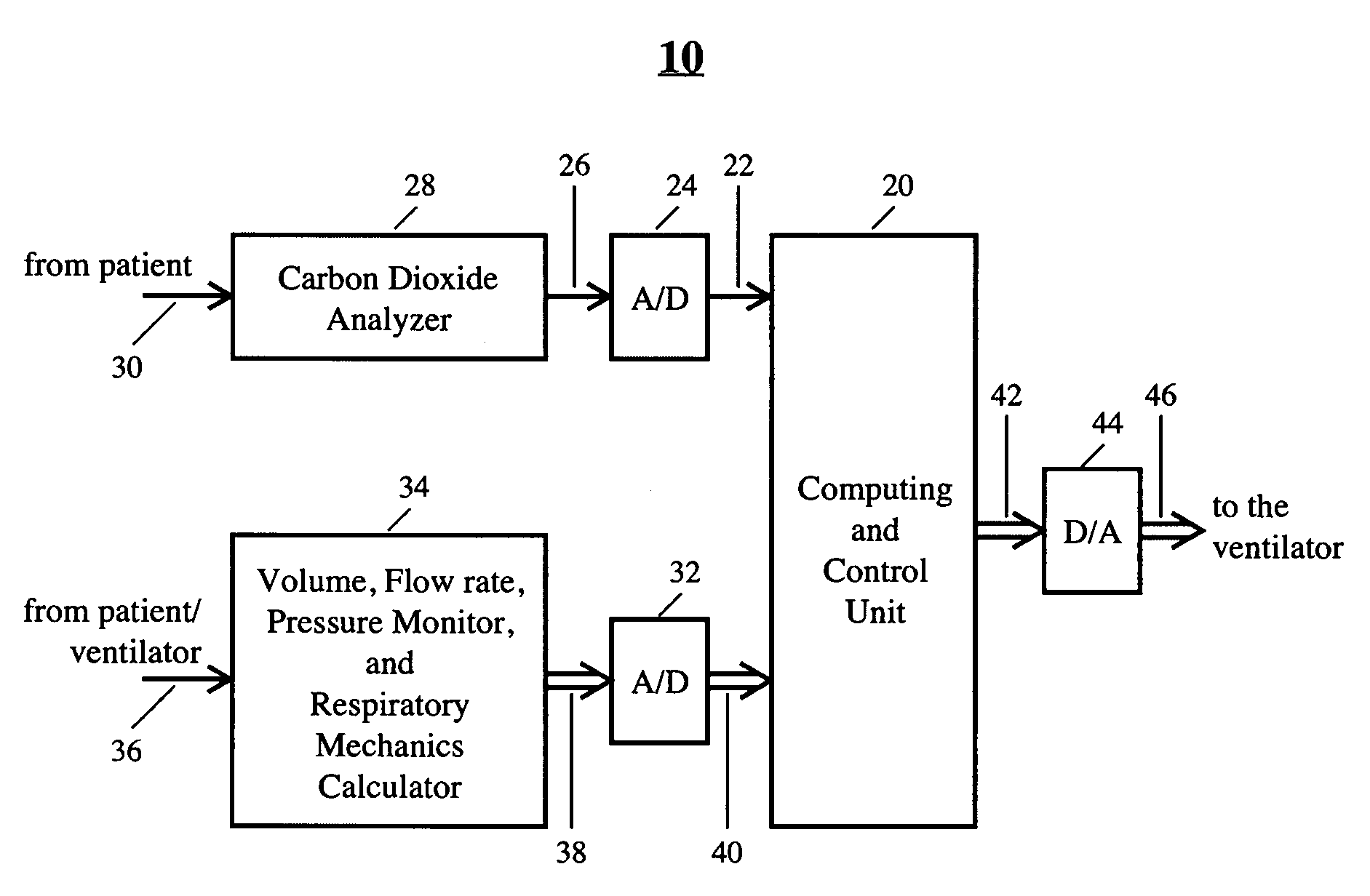
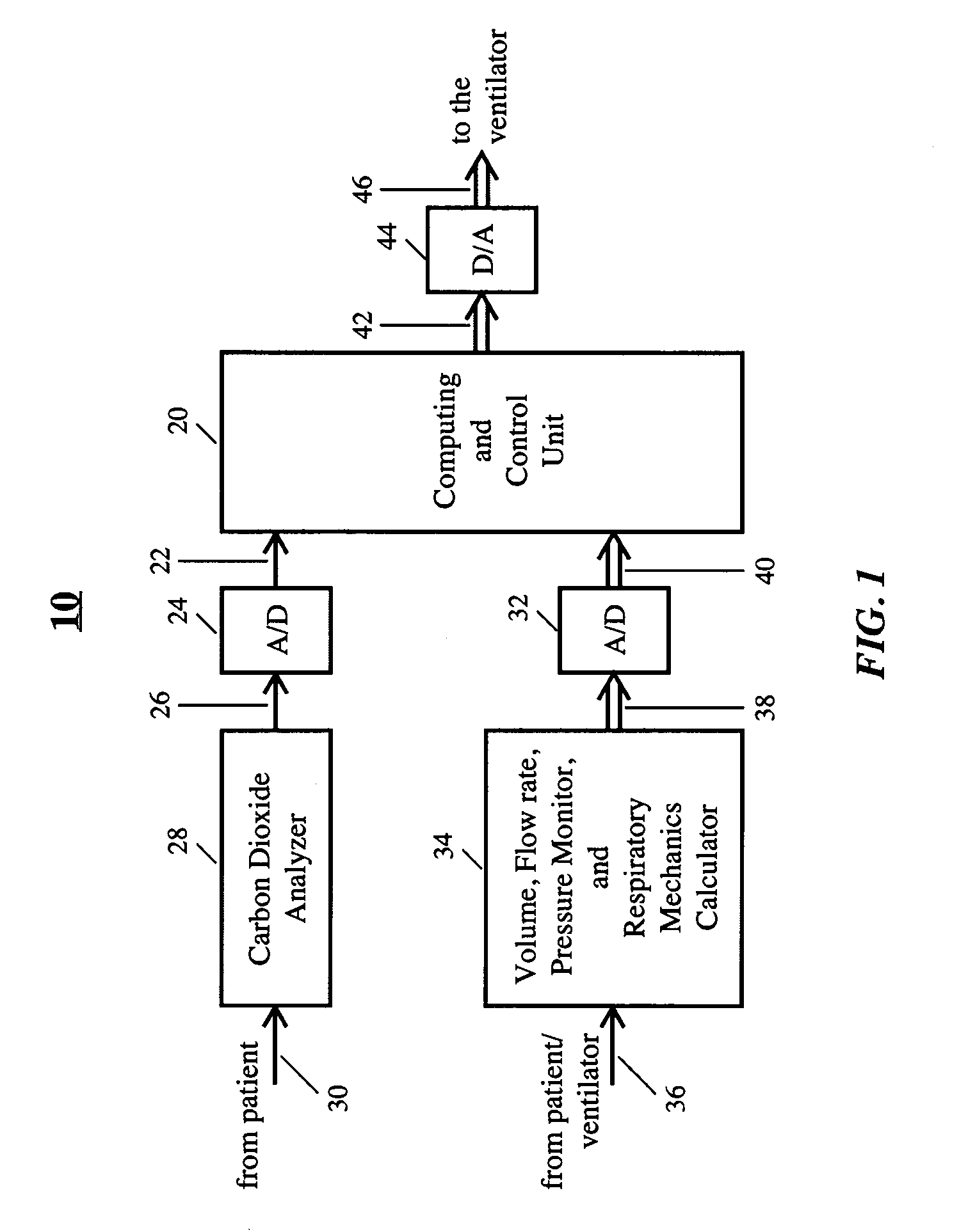
[0046]Referring now to the drawings, wherein like numerals represent like elements, there is illustrated in FIG. 1 a schematic representation of an apparatus 10 for carrying out a method of the present invention.

[0047]A Computing and Control Unit 20 receives input data 22 from an A / D converter 24. The input 26 to the A / D converter 24 may be provided by a CO2 analyzer 28...


PUM


Abstract

A method and an apparatus for controlling a ventilator to automatically adjust ventilation assistance to an active or passive subject. The method includes determining volume and flow rate of gas to the patient during inspiration on an ongoing basis, and generating control signals in proportion to the volume and flow rate of gas to the patient wherein proportionality factors, and support levels for the elastic and resistive components of pressure are automatically adjusted by the ventilator. The ongoing pressure applied by the ventilator is a sum of elastic and resistive pressures that are automatically controlled by the system. When the patient breathes spontaneously, the support levels are automatically adjusted based on the patient's requirements. If the patient does not breathe spontaneously, the ventilator provides ventilation at an optimal level and rate. The method may be used in weaning or in a management phase of ventilation.

Description

BACKGROUND OF THE INVENTION[0001]1. Field of the Invention[0002]The present invention relates to mechanical ventilators, and more specifically, to a ventilator control system that automatically adjusts a supply of breathable gas to an active or passive subject to achieve an automatically determined support level.[0003]2. Description of Related Art[0004]Mechanical ventilation is a treatment technique for provision of full or partial respiration assistance to humans or animals with respiratory failure or those who due to surgeries or various other medical conditions cannot breathe on their own. During the course of this life-saving treatment, it is of paramount importance to provide optimal therapy to patients. The amount of ventilation needs to be adjusted in accordance with patient's requirements and the frequency of delivered breaths should be close to the natural respiration rate of the patient. Provision of inappropriate treatment can cause numerous untoward conditions in patient...

Claims


Application Information

Patent Timeline
Patent Type & Authority Applications(United States)
IPC IPC(8): A61M16/00
CPCA61M16/0051A61B5/0816A61M2016/0036A61M2230/202A61M2230/432A61M2230/46A61B5/091A61B5/087A61B5/085A61B5/0836A61M2016/0033A61M16/0069A61M16/0003A61B5/4836A61M2016/0027A61M16/024A61M16/00
Inventor TEHRANI, FLEUR T.
Owner TEHRANI FLEUR T
Why Eureka
Eureka Blog
Learn More