Network energy balance control system

An energy balance and control system technology, which is applied in the direction of DC network circuit devices, DC power supply parallel operation, electrical components, etc., can solve problems such as increased failure rate, unstable power transmission, and differences in the environment of distributed sites, so as to reduce Failure rate, effect of balanced power output

Inactive Publication Date: 2013-07-03
中国移动通信集团甘肃有限公司
View PDF5 Cites 0 Cited by
  • Summary
  • Abstract
  • Description
  • Claims
  • Application Information

AI Technical Summary

Problems solved by technology

[0003] However, due to the large number of base stations, wide distribution, and large differences in the site environment in the actual application process, a large number of base stations have to be built on wild mountains, commanding heights of private houses, high-temperature and high-humidity areas, etc. for network coverage, resulting in difficulty in power supply Due to attenuation and other reasons during the transmission process of large and high-voltage DC, problems such as power instability when entering electrical equipment lead to increased failure rates, etc.

Method used


Image

  • Network energy balance control system
  • Network energy balance control system
  • Network energy balance control system

Examples


Embodiment 1

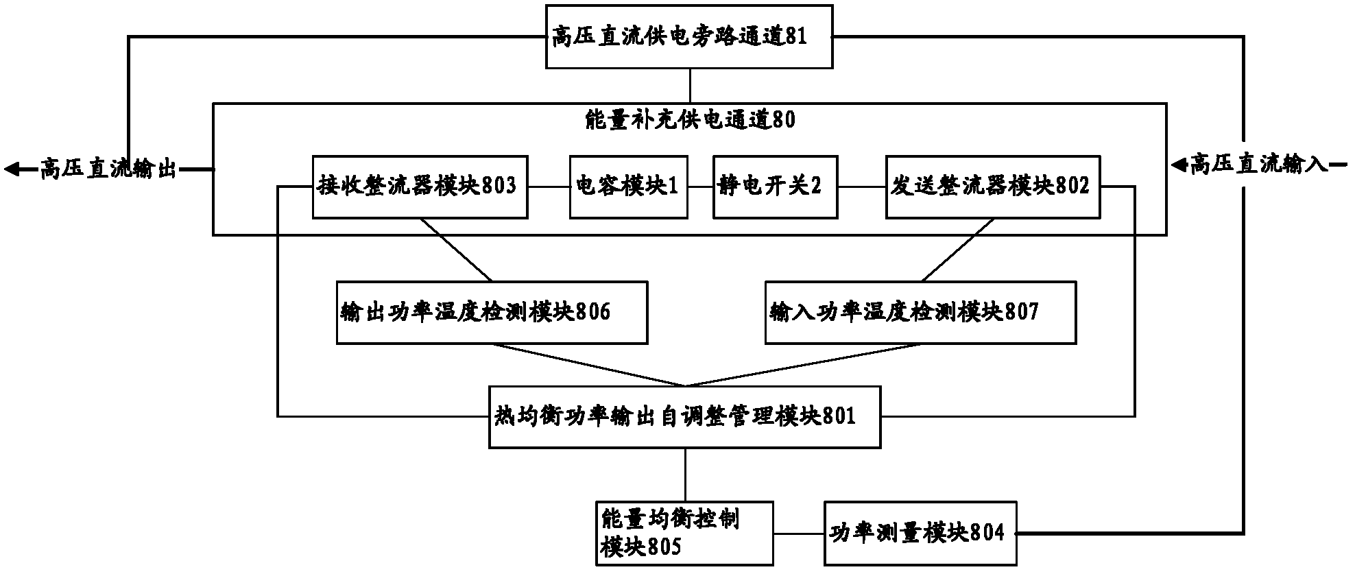
[0042] This embodiment discloses a network energy balance control system, such as figure 1As shown, the system includes: a power measurement module 804 and an energy balance control module 805; a high-voltage DC power supply bypass channel 81 and an energy supplementary power supply channel 80; wherein, the energy supplementary power supply channel 80 includes: a capacitor module 1, an electrostatic switch 2, a transmission Rectifier module 802, receiving rectifier module 803;

[0043] The power measurement module measures 804, which is used to measure the input value of the high-voltage direct current from the local end of the upper stage;

[0044] The energy balance control module 805 is used to compare the measured high-voltage direct current input value with the built-in matrix value of standard current and voltage, and adjust the high-voltage direct current output of the entire system according to the comparison result.

[0045] Specifically, the energy balance control m...

Embodiment 2

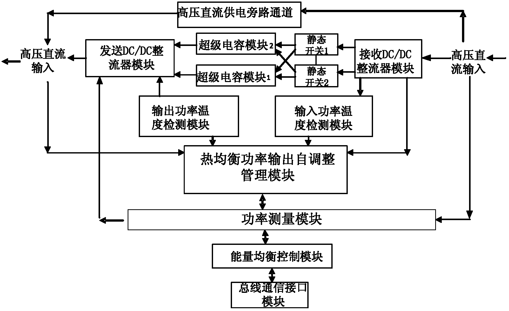
[0068] This embodiment specifically combines figure 2 The scenario shown, describes a network energy balance control system, such as figure 2 As shown, in this scenario, a system for controlling network energy balance is shown. The system includes: high voltage DC power supply bypass channel, sending DC / DC rectifier module, receiving DC / DC rectifier module, 24V super capacitor module 2, 24V super capacitor module Capacitor module 1, static switch 1, static switch 2, input power temperature detection module, output power temperature detection module, thermal balance power output self-adjustment management module, power measurement module, energy balance control module, bus interface communication module.

[0069] The specific working principle of the system is as follows:

[0070] The power measurement module measures the high-voltage input value from the local end of the upper stage, and the energy balance control module compares the measured high-voltage DC input value wit...


PUM


Abstract

The invention discloses a network energy balance control system, and relates to the field of power supply control. The network energy balance control system solves the problem that in the prior art, input values of high-voltage direct current power are not stable in the process of transmission. The network energy balance control system mainly comprises a power measurement module and an energy balance control module, wherein the power measurement module is used for measuring input values of a high-voltage direct current from an upper level local side, and the energy balance control module is used for comparing the input values of the high-voltage direct current and a matrix value of a built-in standard current voltage, and adjusting output of the high-voltage direct current according to comparison results. The network energy balance control system is mainly used for providing power supply compensation.

Description

technical field [0001] The invention relates to the field of power supply control in communication technology, in particular to a network energy balance control system. Background technique [0002] With the rapid development of mobile communication technology, the maintenance of the "heart" power supply of communication is also particularly important. Communication base stations use a DC power supply system to provide energy, and generally use a combined rack power system, equipped with a DC uninterrupted power supply system composed of lead-acid battery packs with online floating charging system. Its supply voltage is -48V. The output current capacity of the rectifier module depends on considerations such as host requirements, battery pack charging requirements, and uninterrupted power supply margin requirements. [0003] However, due to the large number of base stations, wide distribution, and large differences in the site environment in the actual application process, ...

Claims


Application Information

Patent Timeline
Patent Type & Authority Applications(China)
IPC IPC(8): H02J1/00H02J1/10
Inventor 包静毛松苗巩欣
Owner 中国移动通信集团甘肃有限公司
Why Eureka
Try Eureka