
Combined engine

A technology of engine and rotary engine, which is applied in the direction of combustion engine, machine/engine, internal combustion piston engine, etc., can solve the problems of energy consumption, and achieve the effect of uniform power output, ingenious design, and overall compactness

Inactive Publication Date: 2015-06-17
XIAN SHENKE ELECTRONICS RES INST
View PDF0 Cites 0 Cited by
  • Summary
  • Abstract
  • Description
  • Claims
  • Application Information

AI Technical Summary

Problems solved by technology

[0002] At present, in the engine manufacturing and application industries, there are basically reciprocating engines. The main problem is: the direction and compression of the reciprocating inertia consume a lot of energy. This energy consumption is easily equal to the power output. At this moment, the engine power output is zero.

Method used


Image

  • Combined engine
  • Combined engine
  • Combined engine

Examples


Embodiment Construction

[0018] Below in conjunction with accompanying drawing, the present invention is described in further detail:

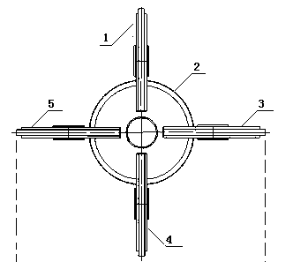
[0019] see figure 1 : A combined engine, its special feature is: the piston and the starter are composed of the piston rotary engine; the piston is composed of the circular crank 1 of the driving disc and the circular crank 2 of the driven disc (a part of the circle is missing), and the axes are mutually Vertical structural form, two circular cranks complement each other to move.

[0020] First, the piston rotates the engine. When the work starts, it is driven by the starter to rotate, and enters the following process:

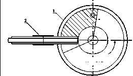
[0021] 1. Inhalation process, such as figure 2 As shown, the horizontal rotation crank is in the vacant position state at this moment.

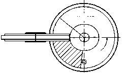
[0022] 2. Enter the fuel injection process. At this moment, the horizontal rotation crank is in the solid insertion position.

[0023] 3. During the ignition process, the horizontally rotating crank is in the st...


PUM


Abstract

The invention relates to a combined engine. Four cranks can generate multiple combustion chambers through shape changes and structure and space changes. A pair of driven cranks and the four combustion cranks are alternated to be combined into a combustion working chamber, so the combined engine is better in skill performance, small in size, high in efficiency, more scientific in design, more stable and evener in low-speed working performance, high in power and large in revolution speed working range. The combined engine is composed of a piston of a piston rotation engine and a starter. The piston is composed of a driving disc round crank and a driven disc round crank (a part of each circle lacks) in an opposite mode, axes of the driving disc round crank and the driven disc round crank are perpendicular to each other, and the two round cranks oppositely move in a complementing mode.

Description

technical field [0001] The invention belongs to the field of engines, and in particular relates to a combined engine. Background technique [0002] At present, in the engine manufacturing and application industries, there are basically reciprocating engines, and the main problem is: the direction and compression of the reciprocating inertia consume a lot of energy. This energy consumption is easily equal to the power output. At this moment, the engine power output is zero. The theoretical limit speed is reached. Generally, the maximum speed power is 1500---3000 / min. Contents of the invention [0003] The purpose of the present invention is to provide a combination engine, so that four cranks can produce multiple combustion chambers through shape changes, structure and space changes, and a pair of driven cranks alternate with four combustion cranks to form a combustion studio , the skill performance is better, the engine is small in size, high in efficiency, and the desig...

Claims


Application Information

Patent Timeline
Patent Type & Authority Applications(China)
IPC IPC(8): F02B53/02
CPCY02T10/12
Inventor 苏西安曹英
Owner XIAN SHENKE ELECTRONICS RES INST
Learn More