A kind of automobile fuel gas supply device
An air supply device and fuel technology, which is applied in the direction of oil supply device, charging system, combustion engine, etc., can solve the problems affecting the uniformity of vehicle power output, uneven distribution of cylinder power, and uneven wear of cylinders, etc. Driving time, good stability, good gas output effect
- Summary
- Abstract
- Description
- Claims
- Application Information
AI Technical Summary
Problems solved by technology
Method used
Image

Examples
Embodiment 1
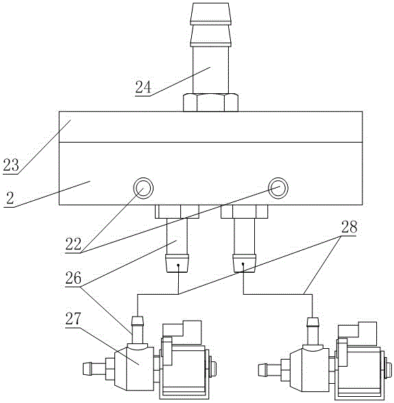
[0031] like Figure 1 to Figure 3 As shown, a fuel supply device for automobiles includes a distribution cavity 10, which is a sealed cavity surrounded by a box body 2 and a cover plate 23, and an air inlet 24 and an air inlet 24 are connected to the distribution cavity 10. A plurality of air outlets 1 also include control parts equal in number to the number of air outlets 1, the shape of the distribution chamber 10 is centrally symmetrical, and the air outlets 1 are arranged symmetrically with respect to the air inlet 24;
[0032] An electric heating block 21 is also embedded in the box body 2, and a hot water flow channel 22 is also distributed in the box body 2;
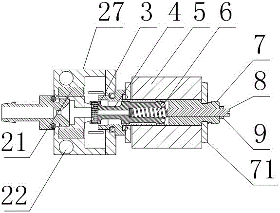
[0033] A connection hose 28 is connected to the air outlet 1, and the other end of the connection hose 28 is connected to a cut-off valve body 27, and a fluid flow channel is arranged in the cut-off valve body 27, and the connection hose 28 is connected to On the inlet end of the fluid communication channel, the ...
Embodiment 2
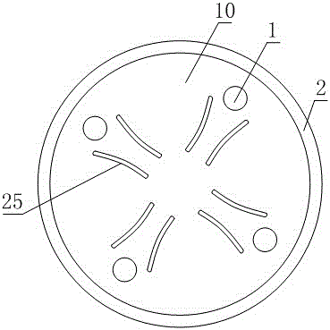
[0038] The present embodiment is further limited on the basis of embodiment 1, as Figure 1 to Figure 3 As shown, as a simple arrangement of distribution chamber 10, air inlet 24 and air outlet 1, the box body 2 is in the shape of a cylinder, and the cover plate 23 is a plate-shaped structure connected with the box body 2 by threads or bolts. The distribution cavity 10 is the hollow part of the box body 2 , the air inlet 24 is arranged at the center of the bottom surface of the box body 2 , and the air outlet 1 is arranged on the bottom surface of the box body 2 and is annularly evenly distributed with respect to the air inlet 24 .
[0039] In order to reduce the influence of the gas outlets 1 during the staggered communication process of the gas outlets 1 after the gas source enters the distribution chamber 10, the bottom surface of the box body 2 or the cover plate 23 can also be provided with groups and gas outlets. 1 equal number of deflectors 25, the deflectors 25 and the...
Embodiment 3
[0041] The present embodiment is further limited on the basis of embodiment 1, as Figure 1 to Figure 3 As mentioned above, the control part includes a cut-off valve core 3, an iron rod 4, a spring 6, a connecting cylinder 7, a threaded post 8 and a coil 5. The ends are fixedly connected, and the iron rod 4 and the spring 6 are all located in the connecting cylinder 7, the connecting cylinder 7 is connected on the block valve body 27, the threaded column 8 is threadedly connected with the connecting cylinder 7, and the threaded column 8 goes deep into one end of the connecting cylinder 7 and The free end of the spring 6 is in contact, the axial direction of the threaded column 8 is parallel to the axial direction of the spring 6 , and the coil 5 is sleeved on the connecting cylinder 7 .
[0042] In this structure, the magnetic field generated after the coil 5 is energized acts on the iron rod 4 to form an electromagnet. When the power is not applied, the elastic stress of the ...
PUM
 Abstract
Description
Claims
Application Information
 - R&D
- Intellectual Property
- Life Sciences
- Materials
- Tech Scout
- Unparalleled Data Quality
- Higher Quality Content
- 60% Fewer Hallucinations
Browse by: Latest US Patents, China's latest patents, Technical Efficacy Thesaurus, Application Domain, Technology Topic, Popular Technical Reports.
© 2025 PatSnap. All rights reserved.Legal|Privacy policy|Modern Slavery Act Transparency Statement|Sitemap|About US| Contact US: help@patsnap.com