Method and a cleaning system for cleaning industrially produced components

A technology for industrial manufacturing and cleaning equipment, applied in the direction of cleaning methods using liquids, cleaning methods using gas flow, cleaning methods and utensils, etc., can solve the problems of indiscriminate laundry, unimportant, and less laundry replacement, etc. Achieve the effect of increasing temperature difference, improving heat absorption capacity and reducing consumption

Inactive Publication Date: 2013-06-19
TMS TURNKEY MFG SOLUTIONS
View PDF12 Cites 9 Cited by
  • Summary
  • Abstract
  • Description
  • Claims
  • Application Information

AI Technical Summary

Problems solved by technology

But the laundry process is a longer process and fewer laundry changes occur, so that the laundry change process can be ignored in the total resource consideration
Furthermore, all t...

Method used


Image

  • Method and a cleaning system for cleaning industrially produced components
  • Method and a cleaning system for cleaning industrially produced components

Examples


Embodiment Construction

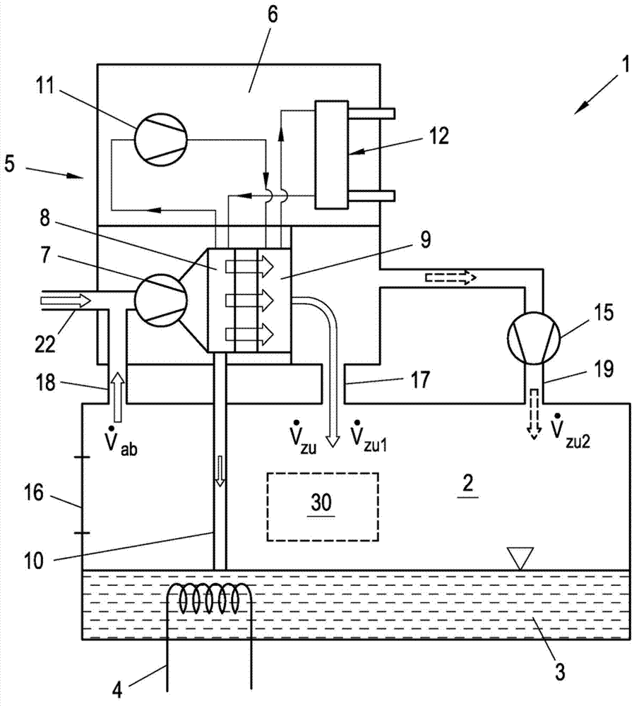
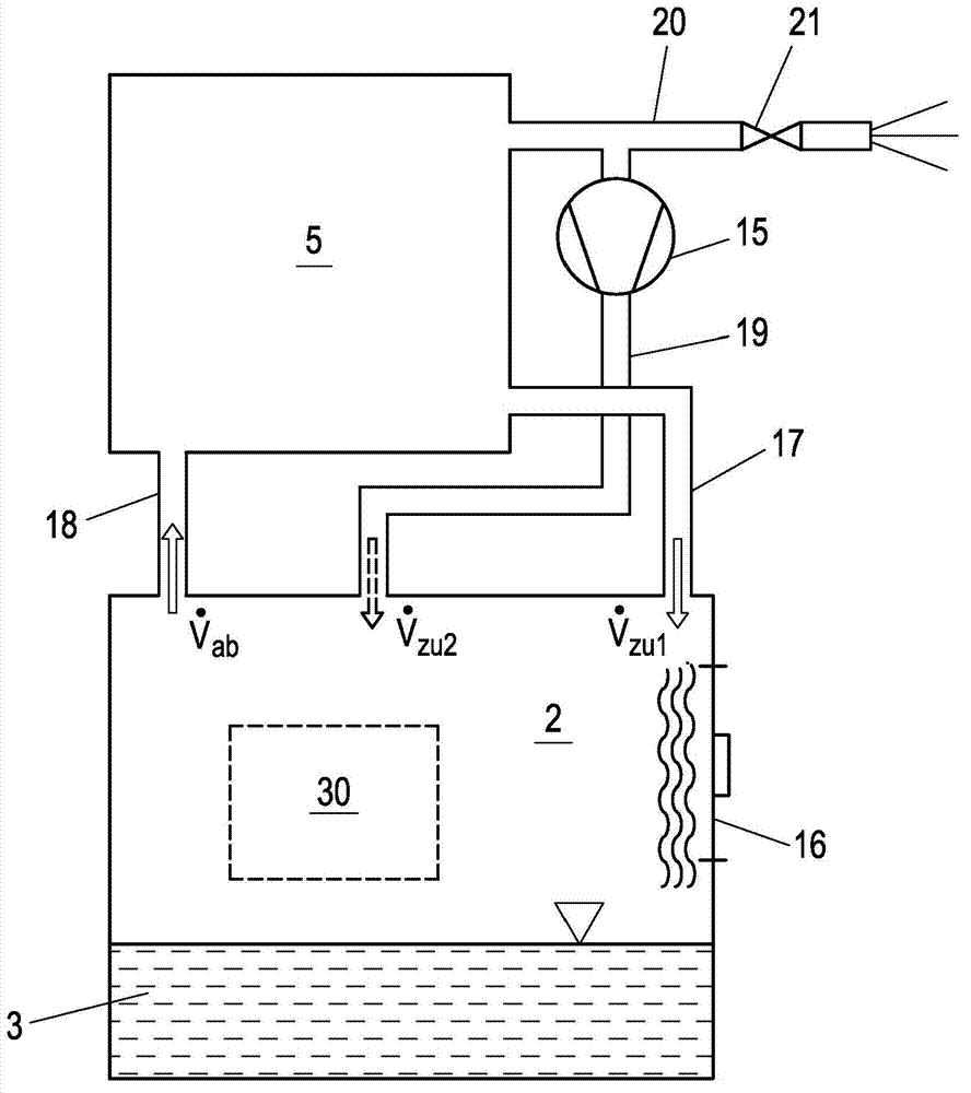
[0019] According to the cleaning device 1 of the present invention, such as figure 1 and figure 2 Schematically described, including a clean room 2, a cleaning agent container 3 and a recovery device 5, in which a component 30 is arranged during operation, such as figure 1 shown. The cleaning agent in the cleaning agent container 3 is kept at a defined operating temperature, for example 65° C. Also can be provided with detergent heating device 4 in detergent container 3 li for this, as figure 1 indicated, e.g. in order to bring the cleaning agent to or maintain the operating temperature. As cleaning agents, for example, water and chemical cleaning agents can be used. The manner in which the component 30 is cleaned in the clean room 2 is not decisive for the invention. For example, spray nozzles can be provided in the cleaning chamber 2, or robot-controlled nozzles or robot-controlled components 30 can be used. As a result of the cleaning process, a cleaning agent mist, ...


PUM


Abstract

In order to recover the resources (cleaning agents, heat) contained in the cleaning agent vapors suctioned off a cleaning system for cleaning industrially produced components, according to the invention the suctioned off waste air (I) is guided in a recovery device (5) via a heat register (9) of a refrigeration device (6), is thereby substantially heated to the temperature of the waste air (I), and the thus heated, dried waste air (I) is supplied to the cleaning chamber (2) in the region of a bulkhead door (16) as preheated, dry supply air (II).

Description

technical field [0001] The invention relates to a cleaning device and a method for cleaning industrially produced components, the cleaning device having a cleaning chamber and an extractor for extracting exhaust gas from the cleaning chamber and a recovery device in which a A cooling register and a heating register through which the exhaust gas is guided and simultaneously cooled and dried, wherein the cooling register and the heating register are part of a cooling machine and the sucked-in exhaust gas is guided through the heating of the cooling machine in a recovery device The register is also simultaneously heated substantially to the temperature of the exhaust gas, and the thus heated, dried exhaust gas is supplied as preheated, dry supply air to the clean room via the supply air line. Background technique [0002] Cleaning plants for cleaning industrially produced components, such as machined components, require a large amount of resources, such as water, cleaning agent...

Claims


Application Information

Patent Timeline
IPC IPC(8): B08B15/02B08B3/02B01D53/00F28D21/00B01D53/26
CPCB01D53/002B01D53/265B01D53/38B01D2257/80B01D2258/02B01D2258/06B08B3/02B08B5/04B08B15/02F28D21/0014
Inventor R·维腾多尔夫
Owner TMS TURNKEY MFG SOLUTIONS
Why Eureka
Try Eureka