Image forming apparatus featuring a controller for controlling rotation of a developer feeding screw in response to an angle of inclination of the apparatus
a technology of controller and developer, which is applied in the direction of electrographic process apparatus, instruments, optics, etc., can solve the problems of unstable amount of toner supplied to the developer container, defective images, and inability to maintain stable toner concentration, so as to maintain constant the concentration of toner
- Summary
- Abstract
- Description
- Claims
- Application Information
AI Technical Summary
Benefits of technology
Problems solved by technology
Method used
Image
Examples
embodiment 1
[General Structure and Operation of Image Forming Apparatus]
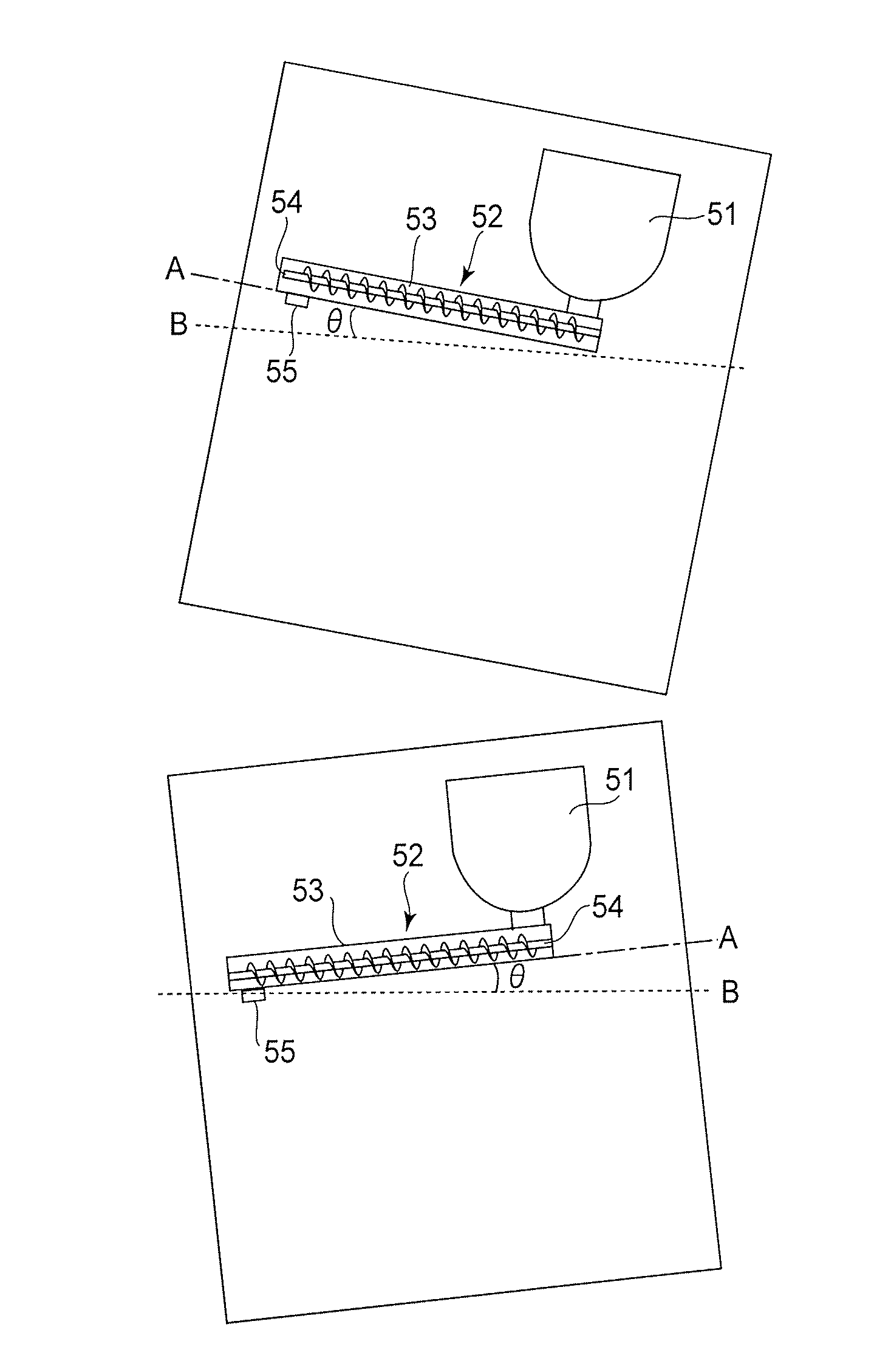
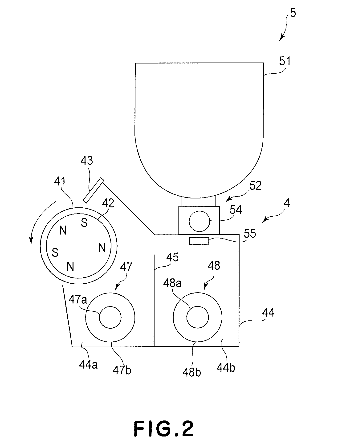
[0031]First, the general structure and operation of the image forming apparatus in this embodiment of the present invention will be described. FIG. 1 is a schematic sectional view of the image forming apparatus 100 in this embodiment, showing the general structure thereof. The image forming apparatus 100 is a full-color laser beam printer, which is capable of forming a full-color image on recording medium (recording paper, plastic film, fabric, etc.) in response to picture signals with the use of an electrophotographic method. The picture signals are sent to the main assembly 110 of the image forming apparatus 100 from a host device, such as an apparatus for reading an original, a personal computer, etc., connected to the image forming apparatus main assembly 110 (which hereafter may be referred to simply as apparatus main assembly) so that communication is possible between the host device and apparatus main assembly 110. F...
embodiment 2
[0104]Next, another embodiment of the present invention will be described. The basic structure and operation of the image forming apparatus in this embodiment are the same as those in the first embodiment. Thus, the items of the image forming apparatus in this embodiment, which are equivalent in function and structure to those in the first embodiment, are given the same referential symbols as those given to the corresponding ones in the first embodiment, and will not be described in detail. What will be described next are the features of the image forming apparatus in this embodiment, which best characterizes this embodiment.
[0105]In the first embodiment, the amount by which toner is supplied is stabilized by controlling the length of time the toner supplying screw 54 is rotated, according to the inclination angle θ of the apparatus main assembly 110. In this embodiment, instead, the rotational speed of the toner supplying screw 54 is controlled according to the inclination angle θ ...
embodiment 3
[0113]Next, another embodiment of the present invention will be described. The basic structure and operation of the image forming apparatus in this embodiment are the same as those in the first embodiment. Thus, the items of the image forming apparatus in this embodiment, which are equivalent in function and structure to those in the first embodiment, are given the same referential symbols as those given to the corresponding ones in the first embodiment, and will not be described in detail. What will be described next are the characteristic features of the image forming apparatus in this embodiment.
[0114]Referring to FIG. 11, in this embodiment, the image forming apparatus 100 is provided with a temperature-and-humidity sensor 85 as an ambient condition detecting means which detects the ambient condition of the apparatus main assembly 110. The temperature-and-humidity sensor 85 is a part of the apparatus main assembly 110. The image forming apparatus 100 is also provided with the in...
PUM
 Abstract
Description
Claims
Application Information
 - R&D
- Intellectual Property
- Life Sciences
- Materials
- Tech Scout
- Unparalleled Data Quality
- Higher Quality Content
- 60% Fewer Hallucinations
Browse by: Latest US Patents, China's latest patents, Technical Efficacy Thesaurus, Application Domain, Technology Topic, Popular Technical Reports.
© 2025 PatSnap. All rights reserved.Legal|Privacy policy|Modern Slavery Act Transparency Statement|Sitemap|About US| Contact US: help@patsnap.com


