Machining method of circular transition section on bottom of central blind hole of generator rotor

A generator rotor and circular arc transition technology, which is applied in the manufacture of stator/rotor body and other directions, can solve the problems of easy generation of concentrated stress, failure to meet the accuracy requirements and performance requirements of the blind hole in the center of the rotor, and achieve the elimination of concentrated stress and meet the surface requirements. Effect of Roughness Requirements and Performance Requirements

Inactive Publication Date: 2013-06-19
SHANGHAI HEAVY MACHINERY PLANT
View PDF4 Cites 5 Cited by
  • Summary
  • Abstract
  • Description
  • Claims
  • Application Information

AI Technical Summary

Problems solved by technology

[0007] The arc transition section at the bottom of the central blind hole of the generator rotor manufactured by the existing technology will leave some obvious knife marks, which is easy to generate concentrated stress, and cannot meet the accuracy requirements and performance requirements for the central blind hole of the rotor.

Method used


Image

  • Machining method of circular transition section on bottom of central blind hole of generator rotor
  • Machining method of circular transition section on bottom of central blind hole of generator rotor
  • Machining method of circular transition section on bottom of central blind hole of generator rotor

Examples


Embodiment Construction

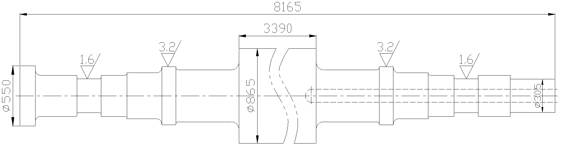
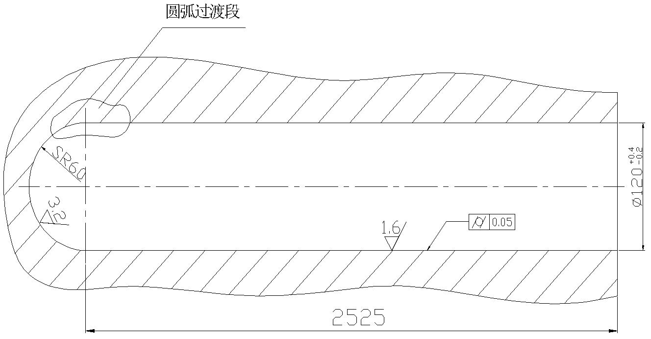
[0032] The processing method of the circular arc transition section at the bottom of the central blind hole of the generator rotor of the present invention is used for processing such as figure 1 , figure 2 For the central blind hole of the generator rotor shown, the length of the central blind hole is not less than 1800 mm, the inner diameter is Ф120 (+0.4 / -0.2) mm, and the surface roughness is Ra1.6; the following steps are included:

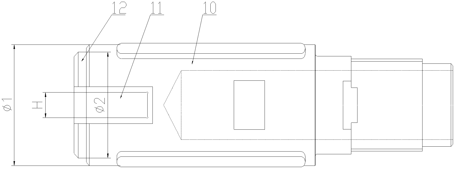
[0033] The first step is to use a deep hole machine tool to nest materials on the workpiece with a nesting drill; then use a boring tool to rough and semi-finish the inner wall of the center hole to form a center hole with an inner diameter of Ф115-118mm; finally use Drill the plate to form a spherical bottom hole with a radius of 57-59mm; at this time, there will be obvious tool marks in the transition section between the center hole and the spherical bottom hole;

[0034] In the process of forming the spherical bottom hole, multiple plate ...


PUM


Abstract

The invention discloses a machining method of a circular transition section on the bottom of a central blind hole of generator rotor. The machining method of the circular transition section on the bottom of the central blind hole of generator rotor is used for machining the central blind hole of the generator rotor, the length of the central blind hole is larger than or equal to 1800mm, the inner diameter pin of the central blind hole is 120 (adding 0.4 or diminishing 0.2) mm, and the surface roughness of the central blind hole is Ra is 1.6. The machining method of the circular transition section on the bottom of the central blind hole of generator rotor comprises the following steps: S1, the formation of a spherical-surface bottom hole, wherein the inner diameter pin of the spherical-surface bottom hole is 115-118mm, and the radius of the spherical-surface bottom hole is 57-59mm; S2, formation of a center hole, wherein the inner diameter pin of the center hole is 119.4mm, the depth of the center hole enables the center hole to be rightly connected with the spherical-surface bottom hole, the surface roughness Ra of the center hole is 3.2; S3, finish milling of the spherical surface bottom hole to enable the steradian (SR) of the spherical-surface bottom hole to reach 59.65mm and the surface roughness Ra of the spherical-surface bottom hole to reach 6.3; and S4, repeated rough polishing, fine polishing and boning of the spherical surface bottom hole and the center hole to reach drawing requirements. By means of the machining method of the circular transition section on the bottom of the central blind hole of generator rotor, lapping defects on the circular transition section on the bottom of the center hole with a 120mm inner diameter pin of the generator rotor can be eliminated, the requirements on surface roughness and performance of the circular transition section on the bottom of the central blind hole are met, and the effect of eliminating concentrated stress is achieved.

Description

technical field [0001] The invention relates to a processing method for a generator rotor, in particular to a processing method for a circular arc transition section at the bottom of a central blind hole of the generator rotor. Background technique [0002] With the rapid growth of power demand, power generation equipment is developing rapidly, and the requirements for the performance of power generation equipment are also getting higher and higher. The generator rotor is an important part of the generator set, a key core part of the power generation equipment, and a bridge for energy conversion. Through the high-speed rotation of the rotor, thermal energy→mechanical energy→electric energy is converted to realize energy conversion, thereby completing the generation of electric energy and Transmission work. Therefore, the technical requirements for the generator rotor are getting higher and higher. [0003] The structure of a typical generator rotor is as follows: figure 1...

Claims


Application Information

Patent Timeline
Patent Type & Authority Applications(China)
IPC IPC(8): H02K15/02
Inventor 陈保霖于大波李视清雷文
Owner SHANGHAI HEAVY MACHINERY PLANT
Why Eureka
Try Eureka