
Narrow bezel-type liquid crystal display device

A liquid crystal display device and liquid crystal display technology, applied in the direction of static indicators, optics, instruments, etc., can solve the problem that it is difficult to provide products with narrow borders and borderless products

Active Publication Date: 2013-06-19
LG DISPLAY CO LTD
View PDF10 Cites 47 Cited by
  • Summary
  • Abstract
  • Description
  • Claims
  • Application Information

AI Technical Summary

Problems solved by technology

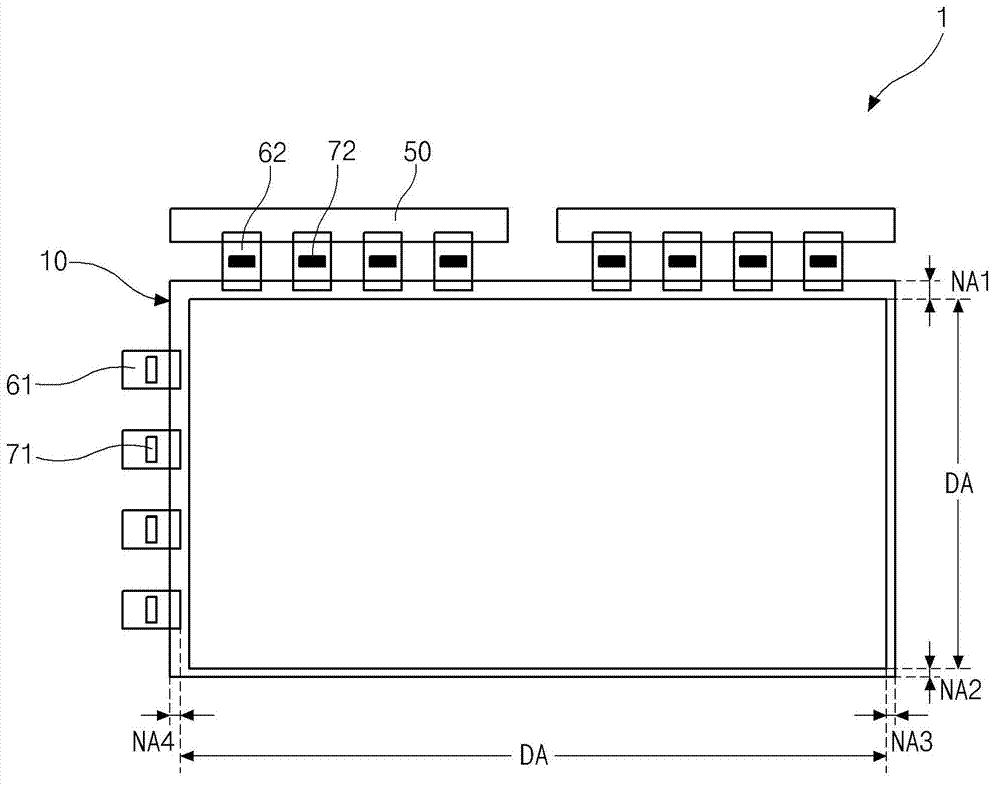
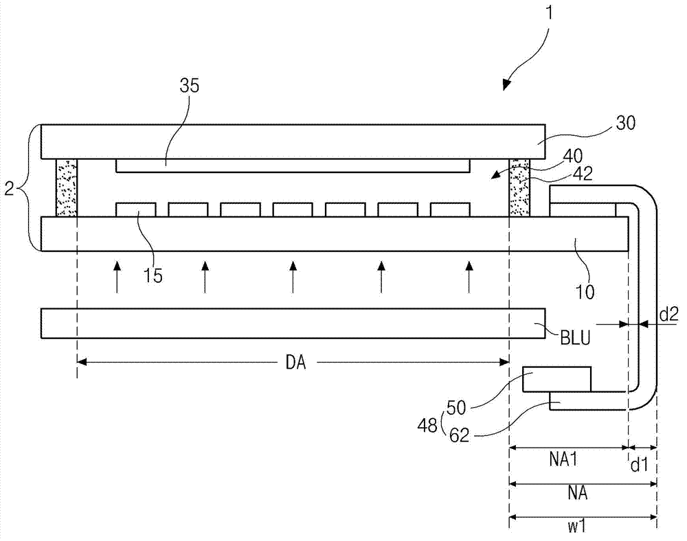
Finally, the width w1 of the non-display area NA of the LCD device 1 is enlarged by a distance equal to the thickness d1 of each FPC 61 and 62 and the distance between each FPC 61 and 62 and the end of the side surface of the array substrate 10 sum of d2, making it difficult to provide borderless products with narrow borders

Method used


Image

  • Narrow bezel-type liquid crystal display device
  • Narrow bezel-type liquid crystal display device
  • Narrow bezel-type liquid crystal display device

Examples


Embodiment Construction

[0037] Reference will now be made in detail to the preferred embodiments of the invention, examples of which are illustrated in the accompanying drawings.

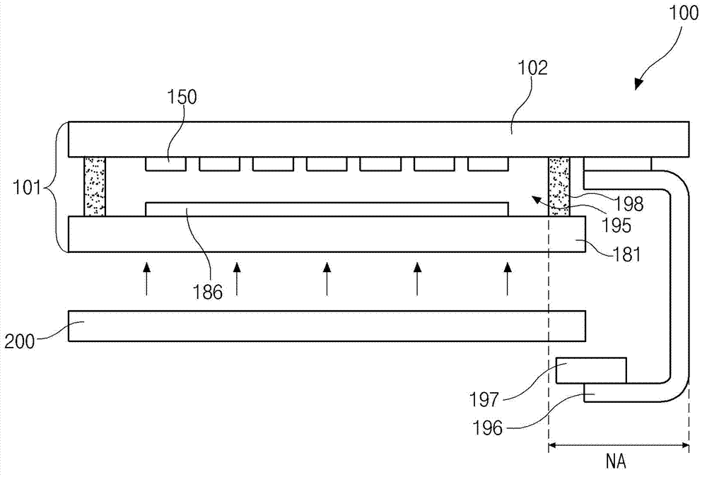
[0038] image 3 is a schematic cross-sectional view of a liquid crystal display (LCD) device according to an embodiment of the present invention, Figure 4 is a cross-sectional view of a pixel region of an LCD device according to an embodiment of the present invention, Figure 5 is a cross-sectional view of a portion where a gate line is formed in an LCD device according to an embodiment of the present invention.

[0039] refer to Figures 3 to 5 , the LCD device 100 according to an embodiment of the present invention includes a liquid crystal panel 101 and a flexible printed circuit board (FPC) 196 . The liquid crystal panel 101 includes an array substrate, color filters, and a liquid crystal layer 195 between the array substrate and the color filters. The array substrate includes a first substrate 102 , gate lines 103 ...


PUM

PropertyMeasurementUnit
reflectanceaaaaaaaaaa

Abstract

An LCD device includes a first substrate including a display region having pixel regions and a non-display region disposed outside the display region; gate lines and data lines on the first substrate and cross each other to define the pixel regions; a TFT in each of the pixel regions; a pixel electrode in each pixel region and connected to the TFT; a second substrate disposed opposite the first substrate; a color filter layer on the second substrate; a common electrode; a liquid crystal layer between the first and second substrates; and an FPC connected to the non-display region on one side of the first substrate, the FPC being bent toward an outer side surface of the second substrate, wherein each of the gate lines has a double structure including a first layer of a transparent conductive material and a second layer of Cu or Cu alloy.

Description

[0001] This application claims priority from Korean Patent Application No. 10-2011-0131149 filed on December 8, 2011, which is incorporated herein by reference. technical field [0002] The present invention relates to a liquid crystal display (LCD) device, in particular to a narrow frame type LCD capable of minimizing the width of a non-display area to realize a borderless product. Background technique [0003] In general, liquid crystal display (LCD) devices operate according to the optical anisotropy of LC. [0004] Specifically, in an LCD device, when a voltage is applied, the molecular arrangement of LC changes according to the strength of an electric field, light is controlled according to the molecular arrangement of LC, and an image is generated. The LCD device may include an upper substrate having a common electrode, a lower substrate having pixel electrodes, and an LC layer filled between the upper and lower substrates. [0005] will refer to figure 1 and 2 The ...

Claims


Application Information

Patent Timeline
Patent Type & Authority Applications(China)
IPC IPC(8): G02F1/1362G02F1/1368G02F1/133H01L27/12
CPCG02F1/1345G02F1/13452G02F1/13458G02F1/136286G02F1/13439
Inventor 张斗熙李政润赵恒燮
Owner LG DISPLAY CO LTD
Learn More