
Method and device of testing surge current impact resistant property of fuse

A technology of current shock and fuse, which is applied in the field of devices for testing the fuse's anti-surge current shock ability, can solve the problems of fuse shock, fuse core breaking, incompatibility, etc., and achieves stable and reliable work, easy setting, precision high effect

Inactive Publication Date: 2013-06-19
CHINA ACADEMY OF SPACE TECHNOLOGY
View PDF4 Cites 24 Cited by
  • Summary
  • Abstract
  • Description
  • Claims
  • Application Information

AI Technical Summary

Problems solved by technology

The actual use of this test device is very limited
The main disadvantages are: (1) There is a switching pulse current in the output. The constant current power supply used by the power supply is to obtain a constant DC current through rectification, filtering, and steady flow of the mains. There must be a switching pulse current with a relatively large peak current. , this switching current can reach several times the normal output current. Although the time is only tens or hundreds of microseconds, it is enough to have an additional impact on the fuse, and even directly break the fuse core.
from Figure 5 It can be seen that the establishment time of the overload current reaches 2ms, which is obviously not suitable for the test where the 600% fusing time is only a few hundred milliseconds

Method used


Image

  • Method and device of testing surge current impact resistant property of fuse
  • Method and device of testing surge current impact resistant property of fuse
  • Method and device of testing surge current impact resistant property of fuse

Examples


Embodiment Construction

[0031] The present invention will be further described below with reference to the drawings and embodiments.

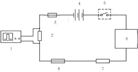
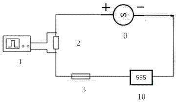
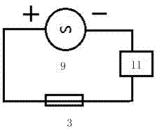
[0032] Example reference of the present invention figure 1 , 4 , 6 shown.

[0033] figure 1 As shown, a device for testing the ability of a fuse to resist surge current impact includes a tested fuse, a monitoring part, a current-limiting resistor, an electronic load, and a power supply. It is characterized in that the monitoring part includes a monitoring oscilloscope and a sampling resistor. The sampling resistor is connected in series with the tested fuse, current limiting resistor, electronic load, and power supply to form a closed loop. The monitoring oscilloscope is connected in parallel at both ends of the sampling resistor. The power supply is a parallel battery pack. The electronic load is used to generate periodicity. When a corresponding current pulse is generated at the sampling resistor, the resistance change and fusing time of the tested fuse are monitored b...


PUM


Abstract

The invention discloses a method and a device of testing surge current impact resistant property of a fuse and can be used for testing the surge current impact resistant property and a fusing characteristic. The technical scheme is that the device of testing the surge current impact resistant property of the fuse comprises a tested fuse, a monitoring portion, a current-limiting resistance, an electronic load and a power source. The device of testing the surge current impact resistant property of the fuse is characterized in that the monitoring portion comprises a monitoring oscilloscope and a sampling resistance. The sampling resistance is connected with the tested fuse, the current-limiting resistance, the electronic load and the power source in sequence to form a closed loop. The monitoring oscilloscope is parallel connection with two ends of the sampling resistance. The power source is a storage battery set, wherein the storage battery is connected in parallel. The electronic load is used for producing periodic surge pulses. The monitoring oscilloscope can monitor resistance variation and fusing time of the tested fuse when the sampling resistance produces corresponding current pulses.

Description

Technical field [0001] The invention is used for testing the current impact capability and fusing characteristics of the fuse, and specifically is a device and method for testing the surge current impact resistance of the fuse. Background technique [0002] In the inductive and capacitive circuit, the circuit will generate an instantaneous surge current when the circuit is turned on. When the fuse of the fuse is impacted by the surge, it will produce a mechanical shock effect of thermal expansion and contraction. In extreme cases, it will be more continuous. The secondary surge impact will cause cracks in the fuse section, or even directly break the fuse, causing the fuse to fail. The invention provides a surge pulse generator, which simulates the surge current impact that the fuse may be subjected to when in use, tests the fuse reliability, quantifies the fuse fusing characteristic parameters, and enables the user of the fuse to further grasp the characteristics of the fuse . ...

Claims


Application Information

Patent Timeline
Patent Type & Authority Applications(China)
IPC IPC(8): G01R31/07G01R31/74
Inventor 苏妤张洪伟张磊于庆奎肖波张莹李强
Owner CHINA ACADEMY OF SPACE TECHNOLOGY
Learn More