
Combined jet flow aeration device

A jet aeration, combined technology, applied in water aeration, sustainable biological treatment, water/sludge/sewage treatment, etc., can solve the problems of complex production process, high production cost, short service life, etc. The effect of contact area, space saving, high oxygen transfer rate

Inactive Publication Date: 2013-06-19
王全勇
View PDF6 Cites 3 Cited by
  • Summary
  • Abstract
  • Description
  • Claims
  • Application Information

AI Technical Summary

Problems solved by technology

The deficiencies in the use of the commonly used jet aeration devices in the prior art are that the manufacturing process is complicated, the production cost is high, the maintenance and replacement are inconvenient, and the service life is short. The aeration devices in the prior art are all made of cast iron, such as continuous Due to long-term use of the nozzle, the wear of the nozzle becomes larger or the caliber becomes smaller due to corrosion and clogging, which will affect the jet aeration effect. Only because one part of the nozzle is damaged, although the other parts are very good, the whole set has to be discarded and replaced: thus causing Use cost increase

Method used


Image

  • Combined jet flow aeration device

Examples


Embodiment Construction

[0016] With reference to the accompanying drawings of the description, a kind of combined jet aeration device of the invention is described in detail below.

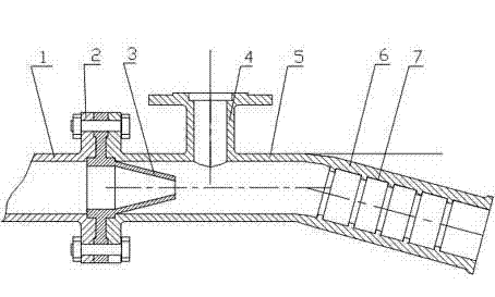
[0017] The combined jet aeration device of the present invention is composed of a high-pressure water inlet pipe 1, a jet nozzle 3, and an aeration tee pipe 5, wherein the right end of the high-pressure water inlet pipe 1 and the left end of the aeration tee pipe 5 are provided with Flange 2, the left end of the jet nozzle 3 is provided with a flange 2, the flange of the jet nozzle 3 is arranged between the right end of the high-pressure water inlet pipe 1 and the flange 2 provided at the left end of the aeration tee pipe 5, and the three are connected by bolts Fixed together, the conical nozzle of the jet nozzle 3 extends into the aeration tee pipe 5, and the air intake pipe 4 is arranged on the right side of the flange 2 at the left end of the aeration tee pipe 5, and the lower end of the air intake pipe 4 is located at...


PUM


Abstract

The invention provides a combined jet flow aeration device. The combined jet flow aeration device comprises a high-pressure water inlet pipe, a jet flow nozzle and an aeration three-way pipe. A right end of the high-pressure water inlet pipe and a left end of the aeration three-way pipe are provided with flanges. A left end of the jet flow nozzle is provided with a flange. The flange of the jet flow nozzle is arranged between the flanges at the right end of the high-pressure water inlet pipe and at the left end of the aeration three-way pipe. The three flanges are fixed by bolts. A tapered nozzle tip of the jet flow nozzle extends into the aeration three-way pipe. A right side of the left end of the aeration three-way pipe is provided with a gas inlet pipe. A lower end of the gas inlet pipe is located at upper right of the tapered nozzle tip of the jet flow nozzle. A right side of the gas inlet pipe of the aeration three-way pipe is provided a bend pipe. An inner wall of the bend pipe is provided with turbulent flow grooves.

Description

technical field [0001] The invention relates to an oxygen-increasing aeration device, in particular to a combined jet aeration device. Background technique [0002] The aeration device is the key equipment for sewage biochemical treatment, and its performance directly affects the treatment effect and operating energy consumption. The deficiencies in the use of the commonly used jet aeration devices in the prior art are that the manufacturing process is complicated, the production cost is high, the maintenance and replacement are inconvenient, and the service life is short. The aeration devices in the prior art are all made of cast iron, such as continuous Due to long-term use of the nozzle, the wear of the nozzle becomes larger or the caliber becomes smaller due to corrosion and clogging, which will affect the jet aeration effect. Only because one part of the nozzle is damaged, although the other parts are very good, the whole set has to be discarded and replaced: thus causi...

Claims


Application Information

Patent Timeline
Patent Type & Authority Applications(China)
IPC IPC(8): C02F3/02C02F7/00
CPCY02W10/10
Inventor 王全勇王新伟
Owner 王全勇
Learn More